The SR7007 caught my eye on eBay. It is still a quite young model (2012) and is technically mostly identical to the 08 Series of 2013. I need preamp outputs and this one had all channels. Nice.
When I switched it on, I heard one click, the display went on and then after about three seconds it switched into protection and the LED blinked rapidly about twice per second.
I suspected a problem with the power amplifier because after the delay normally the speaker relais should switch. Knowing nothing about this device I first tried my luck by isolating (aka plugging off) parts of the power amp board. I got lucky by pulling the high voltage supply. The receiver started and switched the relais after 3 sec. I found nothing suspicious on the power transistors. They all measured identical. Neither did I see any burned parts.
I studied the thing a little more and identified a cable with five lines as the protection signal cable, which goes to the main digital board.
When I pulled that, the receiver would again go into protection, albeit with a different blink code (1x per second).
Now it was time to get the service manual, which is only available for money. 12$ is not a bad price, so I got one and it proved to be worth every penny.
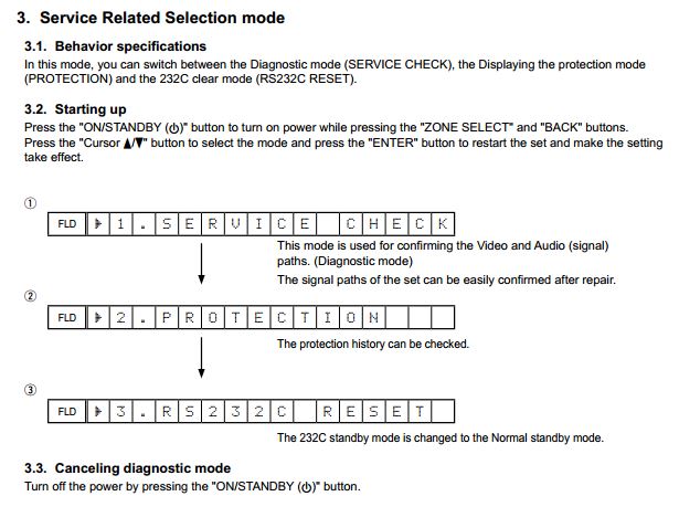
With the high voltage unplugged from the power amp board, the device could be booted in a diagnostic mode where it displayed the last protection error. After the steps in 3.2. shown below, you have to press the Status button on the device. The description is somewhat confusing.
I did that and I got this:
For ASO (no idea what this means), the manual states the following:
Now that did not make any sense. The receiver had never switched the speakers on and neither was there any speaker connected. However, it pointed me to the direction of the ASO protection circuit. Something had to be wrong with it.
Q7001 does a logical OR on all ASO signals supplied by the 7 power channels ASO circuits. The collector signal goes straight to the digital board:
The red line is high voltage plus. It made perfect sense that when this voltage is missing, the ASO protect signal would not go to the digital board. I confirmed through measurement that the transistor switched on during boot. So at least one of the channels must have had a problem.
Now about the actual ASO protection circuit (here: surround back right channel). The marked transistor senses excessive current and when switched on, R7744 passes a plus signal on to Q7001 on the previous image. This circuit is identical in all 7 channels.
The inconvenience was that all the parts for the protection circuit were on the underside of the board. The unit is easy to remove, that was not bad at all. I decided to bend the legs of the power transistors to get access to the underside. Better than unscrewing all of them (horror!)
Now I checked all those 22k resistors, which go from the sensing transistor to the ASO switching transistor's base. And lo and behold, one was off by 3kOhms. The surround back right channel had a problem.
The only possible failure could have been Q7739, the sensing transistor. It measured ok with the diode tester, but it showed a lowered resistance between C and E. I unsoldered it and presto, the resistor R7744 measured normal again. My transistor tester did not recognize the MMBT5551 transistor at all. It showed me two resistors instead.
It is the little guy in the center of the image:
I replaced that sucker and the device went back to normal. A cheap fix, time-intensive and very rewarding. I learned a lot. I always like to improve things after I have fixed them, but in this case I didn't come up with anything. It is hard to tell what happened here as the power stage was still in good shape.
While I was at it I took the chance to adjust the idle current of the power stage as well. It is nicely documented in the manual. The SBR channel was off the most. Was that a coincidence or some further symptom of the incident? I don't know.
About the Marantz SR7007 in general
I never had an AV receiver and I was curious how it worked. Well, the sound is considerably worse than my highly modified Benchmark DAC2, which feeds Focal SM9 active speakers. That was no surprise at all. I have seen its guts and I knew.
What did disappoint me was the image quality via HDMI. One might think that digital signals will not get compromised in digital processing. Not true. The passed-through image definitely lost sharpness to a degree I don't accept it. So that was no option. I am watching movies via my PC and its optical output worked well with the receiver.
The serviceability is not so bad, really. The service manual is very good. The boards, which have the highest expected failure rate (digital board and power amp board), are easy to remove. I think none of the receivers have a bottom lid anymore for an easy checking of the power transistors. They replace whole boards these days and don't mess around.


