No commercial links

Sorry, I had to close comments due to permanent spam. Too much cleanup work.

2016-12-17

Philips 42PFL9803 - Q529.1 LE - flickering image - TCON defect - 1.8V regulator U5 EC50117

This is my first TCON board repair story. This Philips came in with a flickering image. It went completely dark a few times per second.

This video I got from the seller. I suspected a main board problem, it did not look like the panel was faulty.


When the image was visible, it presented very interesting patterns.


Let's analyse this quickly:

  • There are random pixels scattered across bounded areas
  • Some pixels are at the wrong place (the letters in the first image)
  • The panel loses its complete image and goes dark. Some supply voltage might be dropping regularly.

This wasn't a panel fault case as there were no stationary faults. The faults varied with the image structure. The menu generated different distortions than the static from the missing TV signal. Such noise can only be produced by the main board or the TCON.

As it was a lot easier to swap the main and I had one working spare at hand, I tried that first. No change. Then I swapped the also easily accessible dimming board, through which the signal is routed to the TCON. No change either.

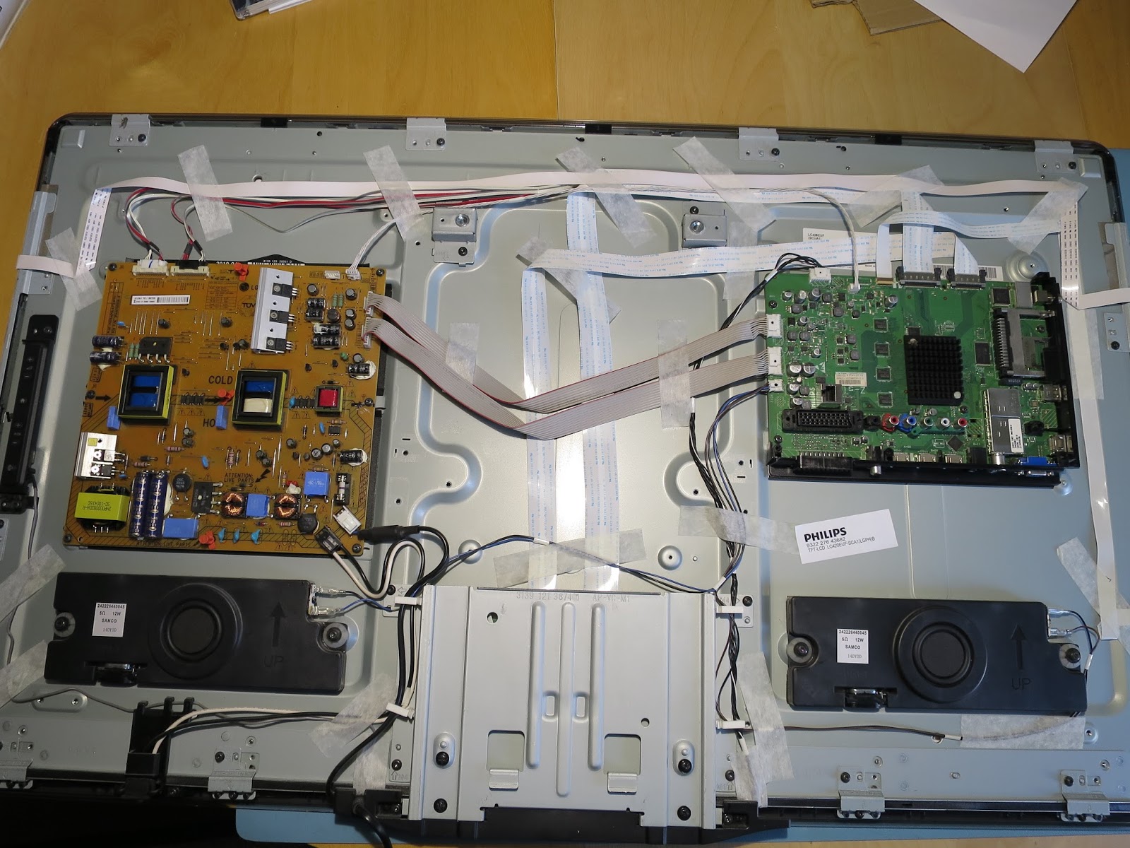
Damned, so I really had to go through the tedious work of uncovering the TCON. It is buried under the sub-frame on which all other boards live. My standard routine to make sure that the panel is not to blame is to unplug each one of the flat cables to the panel. That did not show any static faults in the panel like it would do if address or source drivers were broken. And it still flickered.

The TCON was faulty! I checked all the voltage testpoints I could find, including the gamma voltages of the infamous AS15 chip. The VCC_S and VCC_M where unstable. They should be 3.3V but they swung about 400mV down in pretty much the rhythm that the panel was going blank. I knew I was onto something here. The TCON has two big chips, which are supplied identically. I did not assume that both chips were faulty, instead there had to be a common source of the problem.

I think VCC_S/M are provided by the big chips. The actual 3.3V regulator was absolutely stable.


And I found it. Surprisingly it was the 1.8V LDO regulator for the big chip's core, which was swinging in the same cadence. I think it rebooted the chips all the time and crashed the RAMs, too.


This little sucker is an EC50177 B. It is impossible to get in the TO-252 packaging, not even from Aliexpress. The alternatives in TO-252 I found did not deliver the required 1A.

But before I ordered some spare regulators, I wanted to make sure that this was the only fault. I removed the chip (and broke it to pieces while doing that...) and attached my lab supply. Hooray, the VCC line was rock solid again! The chips pulled around 0.622 amps without glitches.


Now I just had to see the TCON working with the panel attached.


And look at that! A flawless picture :-)

The only 1.8V fixed voltage reg I found from a local source (not Aliexpress again, please!) were LD1086 in the TO-220 package. Fair enough, there was plenty of free space and they are slim enough. And they can deliver 1.5A current. I'd work something out. So I ordered 3pcs from eBay for 7€.

The TO-220 package needed some modifications. I snipped off the tab and bent the legs. With some care it fit perfectly well. I also put a cooling pad on top of it so that it has contact to the cover.


TV working fine. Hallo Frau Green!


This model is built like a tank. It is very heavy, almost impossible to topple over, and the screen is protected by an extra layer of plastic. The ideal device for families with children where things sometimes fly around in the living room

2016-12-10

Philips 46PFL5507 - Q552.4E - DPS130 - dead stand-by - shorted ceramic C910 - open resistor R915 - dead chips DDA010, ST9M101

This Philips did not do anything once plugged in. Not even the stand-by light was on. That's a pretty clear indication of a broken standby supply. I could not measure any voltages coming out of the power supply and quickly concentrated on debugging the stand by circuit.

That was pretty tough. I found out that the PWM chip did not have its required VCC activation voltage. The reason for that was the open 2.2 Ohm fuse resistor R915, which is connected directly to the main capacitor's V+. The diodes all measured ok. The PWM chip had no short, neither had the line, which the resistor was connected to, so I soldered in a 2.2 Ohm resistor to check.


Booom! It took a fraction of a second to kill the new resistor. How is that possible? There was no measurable short and neither did I find any burn marks anywhere.

After some intensive research, I found a schematic in a Russian forum thread, which fit my power supply model DPS-130 well enough. The only component left, which could cause a short, was the capacitor C910. A 1kV 22pF thingy, which did not look suspicious at all. I unsoldered it and voilĂ ! No reading. It was dead, but not with a measurable short. My DY294 transistor tester confirmed the high voltage instability. Amazing how it did survive without any burn marks.

For a quick and dirty test I replaced the cap with a 4kV 33pF and the open resistor again. Supply not working. At least the short was fixed. Thus, the PWM chip must be broken, too. It still did not charge the starter capacitor (which tested ok, by the way) with Vcc. It is responsible for starting itself up once V+ is present at its drain pin. After the startup phase, it would feed itself through a secondary winding in the transformer.

I ordered 22pF 4kV caps via eBay and DDA010 chips via AliExpress. Three weeks later, the DDA010 arrived. I swapped it and the 22pF cap. Supply still not working. The PWM chip did not build up its Vcc startup voltage. I measured again. There was a constant 100 Ohms against ground on the Vcc rail. Under those circumstances, the starter capacitor cannot charge!

The only suspicious part left was IC902, an ST9M101. The original is impossible to find. The alternative part number is Infinno IM1M101-T6G. The documentation of this chip is ridiculous. It is used to sense the presence of the high input voltage. It can disable the PWM chip.


A jumper wire was conveniently located between the PWM VCC line and IC902. I opened it up and finally, the PWM chip was starting. However, it rebooted in a loop. IC902 was definitely defect, too (or maybe the PWM chip had not been dead in the first place). IC902 is also connected to the FB (feedback) line of the PWM chip and I assumed it was causing some trouble there, too.

Ok, another order from Aliexpress. On eBay there are repair kits available with DDA010 + IM1M101 pairs.

Enough with the blondes already, hallo Frau Green!


2016-12-03

Philips 42PFL7685 - boot loop - Software reinstalled - zero cost fix.

This was my first Philips with a software problem. When I switched it on, it would show the "Philips" logo all right, but then it got stuck in a loop. The backlight went on and off in regular intervals.

I opened the cover and the first thing I noticed where a number of dead flies! The device came from a farm village in the countryside and those suckers like it warm :-)


The voltages from the power supply were ok and stable. The only instability I measured there was the BOOST line, which controls the backlight intensity. It went high and low in a loop. That was the reason for the backlight flashing.

So I focused on the main board. All major voltages ok and stable, except the V-LNB (satellite supply), which switched from 11.6V to 19.4V and back. This is intentional during boot and described in detail in the service manual. I also noticed that the audio amplifier chip got muted and unmuted in regular intervals. Both things are controlled by the main processor.

I did not assume that the processor itself was dead, because it did run a program, obviously. A flash ROM maybe? RAM? It very much looked like a software or device configuration problem. Those kind of bugs can sometimes be fixed by reinstalling the firmware.

After an intense study of the service manual I found a technique to update the software blindly:

  • Switch off the device with the mains switch.
  • Insert a USB stick with the software.
  • Press OK on the remote and keep it pressed.
  • Switch device back on. Wait for instructions.

I did that and the TV came back alive. Hallo Frau Johansson!


I've always liked the upper range Philips from 2009-2011 and this one is no exception. How it got hung up by itself is a mystery.

2016-12-02

Philips 37PFL5405 - Q552.1LE - shorted HDMI switcher SII9187

This Philips did not start up and blinked twice. I activated the SDM via the test point on the main board and it gave me error 15:


I know from previous Philips repairs that very likely some voltage required for booting is missing.

This TV is no beauty. The chassis is unnecessarily bulky plastic. The sole reason must have been to make the cheaper series also look cheaper.


So I started main board debugging, which is quite fun with Philips devices due to their excellent service manuals.


I found the voltage regulator 7U03 on the downside, which was supposed to output 3.3V, but all it had was 1.1V. It also was getting quite hot.


Next check: is the regulator broken or the output line shorted? I measured some 500 Ohms on the line. This did not look like a short to me. To be sure, I first lifted the regulator's IN pin off the board and attached my multimeter to measure the current. A whopping 1.2A was flowing, which is way over the spec of the regulator. It was in protection mode and limiting its output current. It had to be a semiconductor, whose short only appears when voltage is present.

So I also lifted the GND pin and soldered a wire to the OUT pin to attach my power supply. Aha, the supply did the same and limited the current.


1 ampere is enough to turn the responsible current sink on the board hot. I moved around with a finger and identified the HDMI chip SII9187 as the culprit. Uh oh. A large quad pack chip in a very inaccessible position.


I managed to remove it without too much collateral damage to the plastic socket holder. Those audio sockets are practically impossible to remove and I figured that it's not needed if I pointed the hot air gun away from them.


With the chip removed, the 3.3V came back and TV booted up fine. That seemed to be its only problem and I was confident to get it fixed with a new chip.

The chip is available only from Asia. I ordered a bunch via AliExpress (3$ a piece). To make the most of the shipping costs I also threw in 5 pieces of its sibling, the 9287 (1$ a piece), because that one is also very common in Philips devices.

Soldering the big quad pack chip tested my patience. I succeeded on second try with the first chip.

Hallo Frau Johansson!


This is not a pretty TV from the outside, but the image is decent. The very thin and squeaky sound is not so exciting, though.

A cheap repair for 3$.

2016-10-21

My lab instruments for testing and measuring

A list of my favorite gadgets for testing my TVs and other devices


Keithley DMM6500

This thing is awesome. There is no other desktop multimeter in this price range with such sophistication. It is super fast and precise. The display is great. It has a touch screen. The continuity test is just perfect (very important feature!). It's best part is the digitizer, which can record voltage or current measurements on a fine-grained time axis. This is fantastic to analyze transients or flaky behaviour of devices when switched on. A scope in rolling mode might do that as well, but the Keithley gives you zooming and all the number statistics. However, setting up the trigger for such measurements is nothing you just do. It requires reading the manual. You can program this thing for specific test scenarios. I've never done that so far. My stuff is rather easy to measure.


EDS CapAnalyzer 88A v2

This tester is in its own league. There is nothing comparable out there. EDS does not build their brilliant testers anymore, like the EDS LeakSeaker, which I recently got as a DIY kit and built it. I was delighted to find the CapAnalyzer on eBay from an authorized seller, who builds them from the original plans. It measures caps in-circuit. And it is resilient against charged caps! None of the testers out there have those properties. They would just die exposed to a charged cap. Look at some videos on YouTube. 

Doing a super quick routine check of all the electrolytics in a device is now possible. No soldering, no speculation by the looks of things. It is emitting beeps according to the outcome of the measurements, you don't even have to look at it while testing the caps one by one! Absolutely brilliant, designed by a real engineer who knows his shit.

It's quite expensive though (and it looks kinda ugly...when engineers design things...), but it is one of those gadgets which you will have for a lifetime.

Update: In the meantime, I got myself a Peak Atlas ESR70 (see below), which is more sophisticated in some aspects, but you can't control the DCR level on that one and it does not have a nice scale for quick assessment.


EDS LeakSeeker 89

Another unique device from EDS. So far, nobody has built anything similar. I put mine into a larger case so that it can be powered by two 9V batteries.

Read all about the build HERE


Grundig RT5A

My trusted companion! Has my back during repairs with exposed "hot" power components like in SMPs. I hovered over eBay for quite some time until I found one in perfect condition.

GWInstek PST-3202

I bought it used from eBay in mint condition for a fair price. It is prohibitively expensive when new. Technically it seems to be a very good supply with sophisticated circuitry. No simple one-chip regulators here, all proprietary stuff with AD-conversion and processor control.

From the usability side, however, it has some drawbacks:
  • The fan is annoying. I already replaced it with a more silent model and put some foam on its frame. The reason for the noise is the speed control, which does not apply a linear voltage, but a pulse signal. This makes it efficient, but the motor engine answers with noise for every impulse.
  • The display is hard to read. The plastic screen is a little opaque and that renders everything fuzzy. Silly idea. Later models have a brighter, white-on-blue display, which might mitigate this a little.
  • The rotary knob doesn't work well with one finger.
  • The terminals are only banana sockets. (Fixed in later model)

QJE QJ12001X

I bought this supply because it goes up to 125V, which is quite useful for LED backlight tests. Apart from that, it is a basic device. When I only need one simple voltage I prefer it over the GWInstek because it is easier to fire up quickly.


QJE PS2002H

This is a brilliant device. A fully equipped supply as big as a multimeter, which does 0-30V and up to 3.75A. As I do a lot of repairs outside my lab, this thing is extremely useful. I did a stress test under full load and it got merely hand warm. Apparently, the switching circuit has very good efficiency.

Be aware! In Komerci's shop at eBay, you get it for 100€. It is also sold under the brand Velleman for twice the price. As of today, this is the only one of its kind.

Unfortunately, it broke down one day without any reason, not even being under load. I swapped the PWM chip and some Opamps with no success. Bought a new one, it is just so useful for repair jobs outside the lab!


Cirtest 3000E

This is my oldest gadget and I love it. I got it as kit from an uncle 35y ago. It is a continuity tester whose tone pitch depends on the measured resistance. It is indestructible due to clever (patented) protection. It won't even mind plugging into the mains. I have used it a lot. It is ideal for super-quick A/B checks and finding connections or shorts on complicated boards. Just sweep over the pins and listen. It also reveals bad (relais) contacts or potentiometers with ease. They will make an unstable or crackling sound.

I think the same circuit is used in the CONTITEST 4000 devices, which come in multiple variants. There is a very decently priced kit: CONTITEST 4000 Kit.

BKPrecision 390A

My workhorse. I am very happy with it. I chose this model because it can measure capacitance up to 20000µ. Very useful for measuring audio equipment.  

Annoyances:
  • It beeps with every action I take  The beeping is ok when the test leads are in the wrong sockets, but I really don't appreciate it for anything else.
  • The very small "m" symbol for mV or mA. I did overlook that a number of times. There would have been plenty of space on the display for a bigger symbol. 
  • The min/max mode is confusing me every time. The thing beeps at me and I don't know why until I switch back and forth to reset it. I am never quite sure whether I did my measurement correctly.
Defects:

I had to clean the switch once because the diode and continuity modes were not reliable anymore. No big deal. Contact spray and polishing the contacts with paper did the job.


Voltcraft R200 milliohm meter

With this meter, you can do four-pole Kelvin measurements in the milliohm range. The device also measures voltages, current, diodes, and capacitors up to 10000µF. I got it used on eBay. I did not work properly out of the box. It would signal a weak battery although they were all brand new. Also, the display appeared weak. I spent some time digging into it, expecting to find some contact problems, until I identified a bad capacitor in a charge pump circuit. No big deal to fix.

The exact same meter is sold also as PeakTech 2705. It depends on your color preferences :-) However, the Voltcraft manual is written much better.

Kelvin measurement at work. A short piece of wire in the milliohm range:


With its six AA batteries, which are required for the 200 mA test current in the 4 Ohm kelvin test range, it will run forever. I am going to use it for my mobile repair sessions instead of the BKPrecision. It is rugged and it only has one (+) socket for V,A,R and C measurements. Might not be the safest solution but it sure is convenient.

The kelvin clips are too clumsy for tracking down shorts on boards. I am planning to build single probes with two wires each. For shorts tracking I don't need absolute fidelity. It is sufficient to have the provided resolution as it is just a matter of comparing values. The lowest value identifies the hot spot.

Blue ESR Meter by AnaTek

Indispensable for testing capacitors. Robust against residual voltages, it can even measure the inner resistance of accumulators to check their quality. I bought it as a kit and had no problem building it. The scale I found in the net and glued it onto the case.

DUOYI DY294 Transistor tester

This is an exotic yet useful device and it is one of a kind. It can measure breakthrough voltages up to 1000V and as a transistor tester it measures the amplification factor. It drives the device under test with higher voltages, which reveals defects under load that are undetectable by any other tester.

I lately found a broken, innocent-looking 1N4148, which measured perfectly ok with the multimeter's diode mode, but had a reverse breakdown of 29V! A good one has around 140V. The only test instrument that could reveal this was the DY294. Worth every cent (it is cheap).

It can also test three-terminal voltage regulators.


BSIDE ESR02 Pro component tester

There are many variations of this tester design on eBay or Aliexpress. The makers of this particular variant had put more thought into the user interface. There is a discharge terminal to the left. There are nice SMD pads, a terminal to plug in wired components, and even little slots where to put SMD parts. After calibration (read the manual, for once :-) it is actually very accurate. Its display is not as pretty as in other models, but who needs colors to display a bunch of numbers?

And it is dirt cheap. A must-have.


LED backlight tester

I watched a video by Shopjimmy where they used this tester to check LED backlights. This was so convincing that I had to get one to be prepared for the increasing number of backlight defects in TVs.

It can generally measure the breakthrough voltages of any single LED, but is also powerful enough to drive LED stripes or even the whole panel and that makes it a brilliant time saver. It produces over 300V if necessary. It comes with needle-pointed probes, which are able to pinch through the plastic coating of LED strips to test individual LEDs if necessary. Nice.

It is available from Aliexpress or eBay for little money. Watch out for cheaper, older versions. I have revision C.

Vellemann audio signal generator

This handy little generator is available as a kit. It produces a sine wave in four steps from 50Hz up to 20kHz. It covers all relevant frequency ranges in audio equipment. The output voltage level is tunable with a potentiometer.

DIY signal tracer & amplifier

I built this with a simple integrated amplifier chip and a DC-blocking and over-voltage protection front-end. It can be used as an active speaker or signal tracer. It runs on a 9V battery. Indispensable for testing all kinds of audio equipment.


DIY transformer ring tester

AnaTek also offers the Blue Ring Tester. This device emits a pulse and counts the damped ringing of a transformer's coil. Each count represents one LED starting with red. It can identify shorted or open transformers or inductors, respectively. I need that so rarely that I decided to build it myself hand-wired instead of buying the kit. The circuit diagram is available for free on the net.


Statron 3229 electronic load

This is one of the gadgets which are sometimes invaluable when you build or test power supplies (like I do). It can be configured to present a constant current load or a constant resistance. Electronic load devices are very expensive when they are programmable. This one isn't, yet good enough for me. You need to use a power supply or a multimeter to adjust it.

The only complaint I have is that the adjustment knobs "fine" and "coarse" are swapped in the constant R section. That's just silly. Apart from that, it is quality engineering made in Germany.


Hantek DSO 1062S

This was my first digital scope. It is portable with a built-in battery, which was the primary requirement for my mobile repairs. Running on battery also has the advantage of being decoupled from ground.

The user interface is somewhat clumsy and takes getting used to. It does a good job with the measurements I do in TV power supplies. It is hackable and mine goes up to 200Mhz instead of the original 60 :-)

It has a multimeter mode, too. It is not a digital storage scope though.


Rigol DS2102A

I had a repair case where I just couldn't figure out what was going on because everything happened so quickly. That motivated me to get a true digital storage scope. For testing power up/down and glitches issues that's the only tool that helps. This thing can do way more than I will ever need or understand. For the occasional user it is actually pure luxury, but well, hobbies, what can you do? :-)

In the meantime, I was able to find a hack so that it has 200Mhz bandwidth now and all the demo features enabled. Pretty cool.


Peak Atlas ESR70 gold & DCA75


During my final build of the EDS leak seeker, I realized that outstanding test equipment is not here to stay forever. One has to get it while it is still available. Therefore, I purchased two of the Peak Atlas gadgets, although I had both measurement tasks already covered.

Peak Electronics to me looks like one of those small companies with a few clever guys, which might not exist anymore in 20 years or so.

The big advantage of the ESR70 over the EDS cap tester is that it measures ESR and capacity, even in-circuit. This simplifies component diagnostics a lot, as sometimes an electrolytic cap's ESR seems fine, yet it could have lost its capacity.

The DCA with its USB connectivity can draw transistor curves, which tells you more about a component than a simple tester does. I will have use for that someday :-)


2016-09-30

Sharp LC-46LE824E - switches itself off when warm - Delta DPS-141CP1A - defect optocoupler in power supply

A friend brought me his Sharp TV with the symptom that it switches itself off when it gets warm. After cooling down it would restart and the problem would repeat itself.

I suspected a cold solder joint, but it was much more detective work. Thermal defects are the hardest.

A look inside:


Nice job, Sharp. Double speakers for each channel and one sub-woofer. Everything easily accessible.

We started testing and after pointing a hot air gun at the output part of the power supply, the device switched off. It recovered after a while and a more precise hot air attack located the area to the down right as most sensitive.

I removed the PS and checked for cold solder joints. None. Everything in good condition. The area around the three semiconductors under the heat sink was very sensitive to heating. The diode in the middle seemed to be the culprit, at least that's what I thought. So I removed the three, unscrewed them from the heat sink, soldered them back in without heat sink and then tested each in isolation. I replaced the diode with no success. The whole area was sensitive, with a tendency to the top towards the optocouplers. I spent a lot of time heating and shooting icing spray without any luck finding the precise spot.


In this Forum article I read about problems with optocouplers, so I narrowed my tests down. And lo and behold, the bottom coupler's sender diode freaked out when heated up. Part number was PC7703. It showed 1.9V break-through voltage at room temperature and quickly lost it when heated up slightly. A cross check with its neighbors settled the case.

Even a slight hot air wind made it fail, that's why I was fooled all the time when I pointed the hot air at other parts in its vicinity. 


I had plenty of spares from scrap boards and soldered in a new one. TV working fine again!

I never had a failed optocoupler. This is very rare. So what was wrong here? Look closely. The coupler sits in the main heat stream of the three semiconductors. And those get very hot! It literally gets grilled. I think this is the reason for its failure.


I glued a little piece of plastic onto the board to guide the heat from below around the couplers. This will relax the temperature situation.


Hallo Frau Johansson!


What I have learned from this case: A part with a thermal defect will reveal it measurably. If a suspected part behaves flawlessly, leave it and move on, even though it is hard to drop a promising fault hypothesis. I measured a double diode isolated from the circuit (forward voltage, reverse voltage) and it did not show any defect. Still I replaced it "just to be sure". It was a waste of time. The optocoupler however immediately revealed its problem very clearly.