No commercial links

Sorry, I had to close comments due to permanent spam. Too much cleanup work.

2018-12-02

Philips 55PFL6158 - 2 blinks - Code 53 - QFU 1.2 - CPU reflow - IR6500 rework station

I am getting the hang of those QFU boards. :-)

Update: I have revived another two of those boards recently with the same symptom by reflowing the CPU.

This Philips did not show any sign of life except for the standby LED, which responded to an infrared remote. The 2-blink would show after a while and the level 2 code in SDM mode was 53.

Quick reminder: if you attempt to repair a QFU Philips, you must have a logging adapter, otherwise you are blind. See this blog post.

I plugged in the logging adapter and I got this in many repetitions until the two blinks came:
....
20:49:53.548 0x00000002 page is reading 
20:49:53.557 0x00000000 0x00000000 0x00000000 StartUnit/EndUnit/offset 
20:49:53.557 Reading out data: 
20:49:53.557 00 unit: 
20:49:53.557 
20:49:53.567 
20:49:53.567 waiting ECC result ready 
20:49:53.567 00 bits error in the unit. 
20:49:53.567 
20:49:53.567 
20:49:53.567 {preboot} 
20:49:53.567 <000> 
20:49:53.567 <010> 
20:49:53.567 <020>K


That was it. Abrubt end.

To learn what was going on in a good TV I logged my 40 inch QFU1.2. The section where the dead device looped should look like this:

20:49:53.567 {preboot}
20:49:53.567 <000>
20:49:53.567 <010>
20:49:53.567 <020>K
KG0G1 
20:49:53.773 <030>DDDDDDDDDDDDDD 
20:49:53.831 <040>secure 
20:49:53.832 Load uboot 
20:49:53.850 
20:49:53.884 
20:49:53.884 U-Boot 2009.01_Production (Jun 11 2013 - 10:29:06) 
20:49:53.884 
20:49:53.884 U�U 
20:49:53.911 NAND: NAND, size:1024MB, Micron(ID:0x2c,0x38), block size:512KB 
20:49:53.913 1024 MiB 
20:49:53.932 Env: NAND @ 0x01800000 
20:49:53.983 bootcmd1 
20:49:53.996 BOOTREASON=coldboot

...

So, the processor could not reach the point where it starts reading the main software, which is actually a Linux boot.

I suspected the SPI ROM first and swapped it. No change. Then I tried the NAND chip with an image from a 40PFL6008. No change.
The last option left was the CPU. I did not dare to reflow the whole board with its uncountable miniscule parts everywhere. I needed a tool with more precision.

I had my eyes on a BGA reflow workstation for a long time and this was the opportunity.
Here it is, the affordable IR6500 made in China (where else).


The preparation of the board was as follows:

  • Remove the heatsink from the CPU. Use a heat gun briefly and it will come off easily.
  • Do not put thick, tacky flux under the chip. I used to do this before, but realized that if the flux bubbles under the CPU while the balls are liquid, this can make the chip bounce and also it can cause balls to connect. Only thin, liquid flux, which does not accumulate under the chip and evaporates quickly, is suitable.
  • Cover everything around the CPU with tin foil. Some instruction videos use a tape. I don't think this is necessary as this device does not blow hot air.
Reflow in progress:


The first test was almost successful. It started booting but something was wrong with the NAND flash that I swapped. Linux refused it. Because the NAND was not the fault in the first place, I put back the original and voila! It started up fine.

Last task: put the heatsink back on. The original adhesive pad got ripped apart. To make the sink removable I decided to glue a thin thermal pad between the CPU and the sink:


The glue stays somewhat flexible, yet it might be strong enough to make removing a glued sink from the chip an unpleasant work. I'd rather destroy the pad instead.

This all worked well. Hallo Frau Johansson!


I do like this TV. The LG panel produces beautiful, realistic colors. My Panasonic Plasma is still the king of skin tone, but I could totally live with this one. With the sharpening reduced to a minimum, that is. I also like that it can be switched to computer mode, which bypasses all extra image processing and pixel by pixel is displayed as is. This gives you a realistic impression which information an image really contains and how much these devices invent by themselves!

The sound is not bad either. The 6000 series is still a bit on the budget side. Stereo is not taking place. The 8000 and 9000 series have a lot more to offer there.

Improving the cooling situation


Philips has undersized the CPU cooling on all QFU chassis. The QFU1.2 is even worse than the QFU1.1. The CPU won't die from that, but the solder balls will break. Interestingly, the 1.1 seems to have different typical faults than the 1.2, yet both are caused by overheating.

This is an image of the back cover from a white 40 inch:


There is some convection going on. The air stream hits the CI socket (bravo!) and exits through a small portion of the upper grill. The dark streaks are dust accumulations on the footprint of the heat sink. Hot plastic attracts dust. This solution relies exclusively on air convection. The infrared radiation hits the plastic and in turn, being a bad heat conductor, the plastic gets hot, radiating back onto the device.

Without the back cover, at 21°C room temperature, the CPU gets 55° hot. That's okay. But with the cover on and in summer I estimate another 20° or more on top of that. That's almost 80°. Too hot for sustained function, if you ask me.

I found no way to attach a larger heatsink to the CPU. There is just no free spot on the board where to fix it.

When I put the back cover on, I noticed that the thermal pad closed the gap between the sink and the cover. That was bad! Thermal death unavoidable and high danger of mechanical shock.

I cut out a rectangle at the sink position and glued a metal grid on it. Nothing beats a sink exposed to fresh air.  Infrared radiation and air convection in one. It is not exactly robust and does not protect the CPU too well, but unusual problems require unusual solutions :-D
There are more stable grids available in hardware stores, but those are are not fine enough.


One hour break-in. About 55°C constant. This is perfect. Identical thermal situation as with an open cover.


About the IR6500


This thing is a little rough around the edges as you might expect from a budget Chinese product.

The manual is funny Chinglish. I could figure out the meaning of most sentences. However, not all details are needed. There is one predefined program for leaded and one for unleaded solder. That's all I need to know. Press start and you are good.

The glass shield on top of the downside heater is bullshit. It reduces the function of the heater plate drastically. The preheating is practically ineffective. I ran the program with the top heater swiveled aside. The board made it to 45°C on the top side. That's a joke. Proper pre-heating begins with 80 or more! I think I am going to remove the glass.

2018-07-29

Philips 42PFL7008 - QFU 1.2 - defect NAND flash? Strange boot looping

Yet another Philips QFU case. This time, the TV got stuck in a boot loop. It would not reach the point where it displays anything.

The first thing to do is to start the emergency software installation. For that, you need an infrared remote, which does not come with the TV. You can get one for around 10€. The reason being that the software, which manages the original radio remote control will not be loaded under such circumstances. Silly Philips!


  • Disconnect the TV from the mains
  • Press OK or DOWN on the remote and hold it
  • Plug in the mains.


I did that and the recovery program came up. Good! This means that the screen, the backlight, and the main processor are doing fine. It can only be a problem with the software or the devices that store it, respectively.

The QFU main software, which I downloaded from Philips, installed fine. The TV went to standby - and did still not start.

Next up: logfile reading. I plugged in my adapter (see this post) and realized that the device is looping. It did not stop randomly while booting, rather it happened at more or less the same moment. The last log message was truncated, no indication that the loop was intended by the software.

This means that the processor always crashed for the same reason. Processors crash due to corrupted software. As I had installed the software previously, I came to the conclusion that the NVRAM chip must be faulty.

In the schematics, the chip is a MT29F8G08ABACAWP. In reality though, it is a MT29F8G08ABABAWP.

It is a 8GB NAND chip.

I was able to to find the binary image of the software. Now I needed a programmer with which to load the software onto the chip, and a supplier from where to buy it.

I got the chips from Aliexpress HERE. It worked fine.

The programmer I chose was THIS MODEL. It also worked flawlessly.


In case you search for programmes yourself, make sure the exact name of the chip is on the compatibility list. The letter soup is confusing and I got it wrong once and bought a non-suitable programmer first.

Swapping the chip was surprisingly easy with my preheater plate and a large nozzle on the hot air gun. In about 15 seconds the chip already floated.

With a new programmed chip soldered in (use lots of flux and a good magnifier glass!) the TV behaved differently. I was able to start it with the remote and everything seemed fine. However I was  not successful each time from standby. It would not listen to the remote everytime.

So I checked the log again and spotted yet another form of boot loop, this time initiated by the software in a consistent and regular manner. The crash was gone, but the TV would refuse to go to standby properly. Instead it first attempts to stop, ambilight goes off, standby LED switches off - and then it reboots into some semi-standby. This repeats forever.

The standby LED actually has three states, which it goes through:

- Dimmed. The TV is not listening. Any command from the remote gives me a quick flickering.
- Off. The TV is not listening. Any command from the remote gives a slow, bright blinking.
- On. The TV will only start in this state.
...repeat from top

A reinstall of the software did not change anything. I also read the boot EEPROM and it was 100% identical to the binary that I have on disc.

I have no idea what to try to fix the loop. The hardware is working. WiFi, ambilight, radio remote, all good.

My only guess is that there needs to be some extra software on the NVRAM chip. Yet, the binary image I got from the Russians was a dump of the chip. I am not even sure anymore whether it is necessary to burn the software onto the chip, because the emergency recovery software will program it, anyway.

So here I am. A TV which is basically working fine, but won't switch itself off to standby. At least I have learned yet another QFU fix, sort of.

Update


I soldered in another NAND with the working software from a 55PFL6158 and now the thing does not even write a log anymore. The CPU gets a little warm and then cools off. This cannot have anything to do with the NAND. It is not even trying to boot. The SPI is good, too.
I tried a reflow of the CPU with no luck.
As it turns out, there is a short on one of the power supply lines for the Fusion processor. This CPU needs a reball and if that's not helping, it is probably toast.


2018-05-07

Onkyo A8470 - speaker relais not clicking - "servo operation" lamp not coming on - degraded glue on protection IC's pins

That was an interesting repair. A friend brought me his Onkyo amplifier. It did not switch the speaker relais on and the servo operation lamp did not come on. Both are controlled by the integrated protection chip Toshiba TA7317 and after some tests and measurements, it became pretty clear that the error had to be there. The amp produced a signal just up to the relais and there was no DC on the output, either.

I remembered a YouTube video where a guy said that in old devices a certain type of glue would degrade and become ever so slightly conductive. Just enough to cause sensitive circuits to malfunction. And what have we got here? A big splash of that brownish gunk right over the pins of the protection IC! They had glued the patch wire to the board with it and splashed glue all over the place.


I cleaned it with acetone and the amp came back to life. I resoldered everything just to be safe that it wasn't a dodgy solder joint.


As a precaution I also took care of the other glue spots:


2017-06-19

Reading Philips TV logs with an USB-UART adapter

With my Philips TVs I never had the requirement to read the log, as they all had measurable faults or the Service Default Mode revealed everything I needed to know. In case of a two blinks error code, which points to the mainboard, or when the TV won't boot at all, it can be beneficial to peek into the log.

You need

  • An USB-UART Adapter. This device maps a serial  (UART) connection across USB to a serial port (COMx on Windows). Device drivers are required.
  • A terminal program, which can handle serial ports.

The hardware


There are various types of USB-UART adapters on the market (eBay or AliExpress). First I tried this type:

Those are garbage. They contain an illegal copy of a Prolific PL2303 Revision A chip, which is discontinued since 2012. Read HERE. The problem is that the latest Windows 8 & 10 driver won't work with it anymore. Some articles in the net say that Prolific has changed the device signature in their later revisions to lock out the copies. You need to install an older version of the driver. I wasted way too much time with this rubbish.

I opened mine up and the chip had no marking on it. Sure sign of a copy. Also, the USB plug already started to come off the board.

So I tried another one with the Silicon Laboratories CP2104 chip:


This one's legit. No driver problems, Windows found the driver itself and the device worked.

The software


On the PC you can use PuTTY. A more sophisticated program is RealTerm. It can record sessions, which is quite useful, and has more features than you'll ever need. Both are free.

The Android app Serial USB Terminal by Kai Morich also works fine. You can read the log on your tablet or phone quickly without a bulky laptop. Just put a micro USB adapter in front of the UART device.


The connection


Now this kept me busy for a while due to my own incompetence.

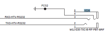
The UART / service socket on the TVs is a stereo 3.5inch type like for headphones. The connections are as follows:


Here is the rub: you need to cross RXD and TXD. Don't connect the RXD on the adapter with the RXD on the TV. Makes total sense once you understand it :-)

A schematic from a ComPair device manual put me on track:


And that's how I built the thing. I attached a 3.5 inch stereo socket to the adapter and used a stereo cable I had lying around:


First tests


I had a working 42PFL9803 sitting in my living room and I tested the device with it. To my surprise I could not get any useful log. The service manual says 38400bps 8N1. I configured everything accordingly and all I got was garbage. The TV sent data but it wasn't readable. I tried many bps setting with no luck. This TV fooled me for quite some time. I thought something was wrong with the UART adapter :-/ I think the older boards use a lower UART voltage level and won't work with this adapter.

Yesterday, I picked up a 32PFL9606 and with this one it worked flawlessly. 


Sweet! I can add one more diagnostic tool to my repertoire. I currently have a 46PFL8007 with the dreaded QFU chassis, which doesn't show any signs of life even though the standby voltage is good. It's not writing a log either. But that's the subject of an upcoming blog post once I have reprogrammed its boot EEPROM, which I suspect.

In the meantime, I glued it into a nice blue box:


2017-06-05

RUNTK5351 TCON - defect analysis - ISL98602

The TCONs with the ISL DC/DC chip notoriously go bad. Sometimes they are fixable by swapping the chip, sometimes they are not. I had the chance to play with four broken boards. Two of them got a new ISL and still didn't work. However, I present you a few tips how to avoid fruitless work, because the main video chip may be measurably dead. Also I think I have measured the reference voltages that the ISL should produce.

The next image shows the voltages of a good ISL chip:


If the voltages are all there and there is still no image, the main chip is dead.

Normally though, the TCONs come with an ISL, which produces no voltages at all. Here are the tests you can do to asses whether it is worth changing:


  • Test 1: In diode mode, measure the breakthrough voltage of the 1.2V trace. It should be around 0.5V. If it is 0, forget the board.
  • Test 2: Attach a lab power supply with 1.2V and current limit around 100mA to the 1.2V supply. The main chip should draw about 0.01A. If not, it is broken.


Alas, I did not yet have a working board in my hand to know how much current the board is supposed to draw from the 12V line. The ones with the fixed ISL and no shorted main chip both pulled 0.39A. The main chip got pretty hot quickly. I guess this is not normal.

Changing the ISL

This is very difficult. I never managed to solder it properly with hot air only. It always took me an extra step with the soldering iron to get the solder to flow at the pins. I failed with a needle tip. It doesn not have enough heat capacity. Spade tips neither worked, even small ones, because they all were too clunky to reach the pins. The only tip that worked was the horse shoe with an excess amount of solder on it. A perfectly rectangular tip would be best. And lots of flux is required, of course.

Be extremely careful with the microscopic SMD parts around it, especially on the upper right corner (previous image). That one 0 Ohm resistor close to the edge gets pushed away easily.


2017-05-25

Philips 46PFL8007 - QFU1.1E LA - no standby LED - Boot EEPROM 7CT3 25P10 reprogrammed

I bought this Philips as defect and didn't ask any questions. The description said it wouldn't switch on anymore. Well, that did not sound so bad. I had fixed another QFU1.1 this year with a dead standby supply.

At pickup the seller told me that the TV had been fixed during warranty with the same symptoms. The mainboard was the culprit then. Uh oh...

When I plugged it in, the standby LED did not light up. Standby voltage was present. The LED is controlled by the main processor (the standby processor section). The only voltage the stdby proc. takes in is the 3.3V standby. Nothing else. The LEDs are fed with the same voltage.

I studied the service manual thoroughly and the only conclusion was that the processor was in trouble. I ran a reflow session in the oven. Did not help.

In the Iwenzo repair forum, I got the hint to reprogram the standby software flash ROM. For that you need two things:

  • The software binary for the QFU1.1 platform SPI boot EEPROM. Version 77.02.
  • An EEPROM programmer.
My adventures with the UART adapters you can read HERE. This TV did not produce any log whatsoever. The CPU was not running any boot program.

I also purchased an EEPROM programming device called SkyPro USB Programmer. It is made by Coright. The software installed flawlessly on Win10. I had to desolder the Flash ROM 7CT3 and solder it on an adapter board, which then went into the programmer's socket.

The chip sits under the upper right corner of the white heatsink. The sink has to be removed carefully. It is mounted with two spring bolts, which are easy to release, and an adhesive foil. The foil does not survive the process.

I tried a test clip from Aliexpress first directly on the board. This was like lottery. The clip did not attach properly and I got only nonsense results.

The software then identified the Flash as 25P10 (128k) instead of a 25MP05 (64k), which is listed in the service manual.

Now, the hardest problem was to find the right software as there are a number of versions floating around in the net. The QFU1.1 has two variants. One for Fusion 67.0.0 and one for Fusion 77.02.08. This device needs the 77 version.

The 77.04.08 is QFU 1.2 and will not fit. It is used in the xxx8 series, not the xxx7.

To add to the confusion, 77.02.08 is also supposed to work for QFU 2.1. This is only used in the 6007 model, however.

This is the software that worked for me: DOWNLOAD

A peek into the binary files

The first diff shows the good file to the left, which finally revived the set, and the scrambled one to the right, which I read from the EEPROM initially. You see that the first block is wiped out with garbage. There were more garbled blocks further up the address space.


The second diff shows the Fusion 77 to the left and the Fusion 67 to the right. If you have a file at hand and like to investigate which version it is, take a HEX viewer and study the first block.


Notes


I first did not realize that the TV was actually fixed because I didn't insert the flat cable to the TCON properly. It looked totally fine, yet it wasn't sitting right. The sockets on the mainboard have a locking mechanism. You need to push the two black knobs down. I failed to do that and broke off the locking nose on the cable. The cable then does not sit very well anymore.

The TV was stuck in a boot loop because of the cable. The log displayed weird errors about the DVB-S tuner. In hindsight, it must have been trouble with the I2S bus.

I stumbled over the solution while testing another board where I made the same mistake with the cable again! This time I caught it rebooting immediately after I had touched the cable.

I once destroyed a not properly seated cable. A trace went up in smoke. Be very careful with those.

Don't forget to plug all wire harnesses into the mainboard. If the WLAN is missing, you will also get a loop.

So what is going on with those QFU chassis?


A number of devices with similar symptoms are mentioned in repair forums and sold on eBay/classifieds. What's going on here? How can an EEPROM, which is otherwise fully functional, lose blocks of its memory? What I know is that the processor gets really hot. I measured 57° celsius at 21° room temperature with an open back cover. Now extrapolate that to 30° and closed cover. I recon it will be 70° or more. Does the EEPROM get grilled? I don't know.

2017-04-02

Panasonic TNPA5330 SN board 7 or 6 blinks - detailed fault analysis and repair guide (TX-P42GT30, VT30, ST30)

I received a TX-P42GT30 with the famous 7 blink disease and it is the fifth Pana plasma with this defect. I am going to present my analysis of the causes of this defect, which appears after four to six years. On eBay I am seeing more of them these days.

The actual cause are loose screws. Why did they get loose? Because of the solder on the contacts. Solder is soft and flows under pressure. Why is this troublesome? Some screws and their contact pads conduct a lot of current into the metal panel chassis. When they become loose, the contact resistance increases and sparking occurs. This in turn leads to very high current peaks, which eventually kills (shorts) a diode. It is also possible that the increased resistance causes the mounting area to heat up and that kills a diode. This diode connects six transistors and another diode and those die immediately.

The next image shows the troubled screw position in close-up. It takes the full current from the DAF30 diode to the panel chassis ground. Other screws, which I'll show you below, pick up the current and from there it flows back to the power supply. Notice how the legs of the diode are discolored through heat! This one got enormously hot:


The mounting hole backside under the microscope. We see blackened, burnt solder:


And this is what a mounting point looks like:


As long as the screws stay under tension, the contact to the chassis will be good.

In the 60 series, Panasonic has learned from the screw disaster. This is an image from a 55STW60. No solder on the holes and screws with spring washers!


They also finally stopped using SMD power transistors and returned to decent heatsinks. Who needs silly super-flat TVs, anyway? I think those scan boards are built for eternity - maybe, provided the capacitors, which get all the heat from below, are holding up well.


In the next image, I marked the other screws, whose holes also had burn marks. The two on the top pick up the current from the chassis, which enters through the screw in the center. You see the already repaired board with my choice of transistors and diodes (see this post). Other screws have a proper bracket on the board or don't carry much current. There, the contacts looked ok.


And here is the section of the circuit where you can see all the affected high-power parts in one glance. The DAF30 diode is marked yellow. The diode and three transistors to the left and the three transistors to the right next to the troubled diode are all shorted when disaster strikes.


From 7 blinks to 6 blinks


6 blinks indicate a problem with the MIR voltage, the energy recovery voltage, which builds up across the blue C631. It must stay in a corridor around 120V.

Dead driver transistor array and control chip (energy recovery H section)
Strangely, a driver transistor plus its control chip die, even though they are not responsible for any of the shorted power transistors. Q441 is still ok, yet those two are dead. I wonder why, but I have observed this twice already, only in 42 inch models though.


Broken IGBT (energy recovery L section)


The boards I have repaired also had a less obvious failure in Q451, a DG302 transistor. It has no dead short, but in diode test mode, it will leak between collector and gate and show a break-through voltage on the multimeter. It may not have this fault at the beginning and develop it once the other defects are repaired and you switch the device on for the first time! But don't worry, it will not destroy any other parts. It is best to routinely replace it.

See also below where I describe how to debug the recovery section.

How to repair this defect properly

  • Replace all broken components
  • Remove all solder on both sides of all screw mounting holes. Only apply a very thin and flat(!) layer of solder. It helps making a good contact.
  • Clean the mounting points on the panel chassis from all black residue.
  • For the screw next to the DAF30 diode and the two on the top, replace the original screws with ones with a spring washer. Make sure they are not too long, otherwise you will drill into the panel! The screws will not loosen much once the solder is gone, but for the critical ones I want extra safety.

Debugging the 6 blinks of the energy recovery circuit

Through my own stupidity I damaged an already repaired board and spent hours trying to find the reason for the 6 blinks. The device started, the green LED on the SN board briefly came on and then it immediately shut down. Not enough time to take measurements with a voltmeter. A not 100% working driver transistor was the culprit. Along the way I learned a lot about the circuit.

Get the manual for the TC-42GT30 from elektrotanya.com. This manual is top quality with zoom-able schematics. Page  69, chapter 12.27 SN1 Board Schematic Diagram. I have another for the TX-42 with pixelated graphics, where you can't read the part numbers.

The recovery voltage can be measured across C631. It should be around 120V. The protection activates below 36V and above 157V. The polarity is not important, just focus on the amount.

A multimeter in MIN-MAX mode may not be fast enough to catch the max amount. I used a digital storage oscilloscope in roll mode with 1ms time base. It showed the ramp-up of the voltage beautifully. However, this is not required, because if the protection circuit fires, there are only two possible cases, which a quick multimeter can detect in MIN-MAX mode:

If the voltage is missing, the recovery L section is not working. Most likely, Q451 has a problem as described above. Mine never had a full short. If it has, also replace Q551 and IC522.

If the amount is too high, the recovery H section is not working. Strangely, Q441 does not die, but its companions Q531 and IC502. This is a total mystery to me.

Spare parts

The driver IC I got from  HERE and the transistors from HERE. So far, they seem legit and work ok.

In THIS BLOG POST I talk about possible replacement for discontinued parts. I am trying my luck with the FGD4536 for all the power transistors, including the DG302.