The seller of this TV said that it would start and work properly when switched on via the main switch, but neither the remote nor the buttons at the TV had any effect. Also, the standby light wasn't illuminated and actions on the remote would not make it flicker.
The Philips support told her that a new main board was required. That was basically accurate, as we will see.
Now this did sound like a clear case of broken power supply of the control board, which links the remote sensor and the buttons.
A look inside. Lots of wiring. Good speakers!
This is the control board with the remote sensor. The left cable is coming from the buttons. The right cable goes to the main board.
Here we have the socket on the main board. Can you see how strangely imprecise it is mounted?
I shifted it a little bit and switched the TV on. It was working! The stand by light was red, the remote control did its job.
Aha! A look on the B-side of the main board revealed the problem. A production error with a terribly bad solder joint, which goes to ground. It took five years to finally break. And look at all that weird residue around it!
I reflowed everything, cleaned it up, tightened a number of totally loose screws of the power supply and the pretty little sucker was good to go :-)
No commercial links
Sorry, I had to close comments due to permanent spam. Too much cleanup work.
2016-05-12
2016-05-08
Philips 42PFE0001D/H - distorted colors - defect AS15F chip on TCON board
Another AS15 repair :-) I was interested in this Philips TV, because it once was the absolute High-End. It has an external box with the power supply and main board. Two cables go the monitor, which contains the logic board, TCON and inverter.
The seller liked it so much that he offered to buy it back if I managed to fix it. Fair deal.
Switched it on and got this:
Really bad color distortion. The Menu titles even disappeared sometimes into the dark. A typical AS15 gamma chip fault.
Not much in the monitor:
Funny idea: a heat conducting block for a back cover made of plastic. Well, it worked for 7 years, so it wasn't that stupid, I suppose.
And here it is. The blue TCON board of doom made by AUO. The chip is on the upper right.
Time for gamma measurements. In brackets are the values of the new chip. Three test points were far off.
vgama1: 15V (15.5V)
vgama2: 14.7V (15.4V)
vgama3: 10.5V (10.8V)
vgama4: 10V (10V)
vgama5: 9.7V (9.8V)
vgama6: 7.7V (7.7V)
vgama7: 7.7V (7.7V)
vgama8: 7V (6.9V)
vgama9: 7V (6.9V)
vgama10: 9.2V (5V)
vgama11: 5.8V (4.7V)
vgama12: 10.7V(4.0V)
vgama13: 0.43V (0.36V)
vgama14: 0.38V (0.33V)
As always the heat conducting block stuck to the chip and broke off. I think we have a pattern here. It looks as if the material had disintegrated. Maybe that sealed the death by heat of those chips.
To solder the chip I used my new horseshoe solder tip and it worked fantastic. Much better than the spade type I had used before.
That's much better!
Perfect grades of black:
Being curious I peeked into the so-called hub, the control unit. I couldn't figure out how to get to the power supply below the main board. The chassis would not come out and I decided not to mess around with stuff that works. I just blew out the dust from the cooling fan on the left.
Hallo Frau Johansson!
2016-05-03
Philips 42PFL8654 - no standby voltage - two shorted SB260 diodes - Power supply DPS-298 ticking noise
This Philips 8000 series of the generation 4 came in dead. It wasn't starting, no sign of life. This pointed to a stand-by power supply problem.
With the multi-meter in continuity mode I quickly located two shorted diodes on the secondary side of the stand-by supply. The diodes were Vishay SB260. I probed around the supply lines for shorts and found nothing. This is strange. Why did both of the diodes die? Maybe one blew first and the other would not hold on for much longer due to overload. I have never seen two diodes in parallel in any power supply so far.
I checked eBay with the power supply board id DPS-298 and a number of repair kits came up! One contained the two diodes and the four caps. I ordered one, even though I was not convinced that the caps were the culprits. For 5€ there is not much harm done.
Compared to various images on the net and on eBay
like here:
my caps looked like new. I wonder why they burn up like this. I better not measured their temperature, for it is high voltage which either hurts me or destroys my meter.
I first located the noise in the transformer (because my mind said that it was logical) until I switched the light off to see if there were visible sparks. Nope. Nothing to see. Being blind, my ears overruled my mind and found the real noise source: The 0.47µF cap, which goes to ground from the test point.
The cap could not be the source of the problem, because it goes to ground and the measured pulse increased the voltage. However, the sudden voltage spike caused mechanical noise in the cap.
The two FETs are in a half-bridge configuration and they were my new suspects, because they control the voltage to the primary winding. Maybe one had intermittent failures?
With the multi-meter in continuity mode I quickly located two shorted diodes on the secondary side of the stand-by supply. The diodes were Vishay SB260. I probed around the supply lines for shorts and found nothing. This is strange. Why did both of the diodes die? Maybe one blew first and the other would not hold on for much longer due to overload. I have never seen two diodes in parallel in any power supply so far.
I didn't have those diodes or similar on stock, but some BYV29 ultra fast diodes were available. One of these can cope with more current than two of the little ones, so I gave it a shot.
Plugged the TV in and it started just fine. The image came up all right. That was too easy, I thought. I left the TV running for about two minutes and suddenly, an intermittent ticking noise like from a Geiger counter came from the high voltage transformer, which feeds the backlight. A cold solder joint? I reflowed all the critical joints, even though none of them looked suspicious. As expected that didn't fix it.
So, those were the possibilities:
- The transformer had an intermittent short. I would expect it to go up in flames if that was the case.
- Some other weird problem with the transformer.
- At least one those blue ceramic 6kV capacitors was about to die:
I unsoldered all four caps and measured them with the capacitance meter. All had their specified values. Then I pulled out my funky Chinese DUOYI DY294 transistor and cap tester to check for break through voltage. This little device can produce high voltage and test whether a part withstands it or not, using 1mA leakage current.
All caps measured similar with about 1450V. I didn't know what to think about that. They are rated 6000V. It was outside the spec of the tester (max 1000V).
As all caps were identical in that respect, I concluded that a fault was not measurable with my equipment. The output of the transformer produces much higher voltages, so it was still possible that at least one cap was faulty. Or I was on the wrong path altogether and the transformer was bad.
I checked eBay with the power supply board id DPS-298 and a number of repair kits came up! One contained the two diodes and the four caps. I ordered one, even though I was not convinced that the caps were the culprits. For 5€ there is not much harm done.
Compared to various images on the net and on eBay
like here:
or here:
my caps looked like new. I wonder why they burn up like this. I better not measured their temperature, for it is high voltage which either hurts me or destroys my meter.
This thread discusses the same problem my TV had:
http://www.badcaps.net/forum/showthread.php?t=35814
After a night's sleep I doubted that the four caps were responsible for the noise. I started measuring a little more. The inverter drives two windings in parallel. The primary side looked like it had a center tap, but the two coils are arranged symmetrically. The circuit is a mystery to me. The outer transformer pins are driven against ground and V+ by the FETs. The inner pins are coupled via 0.47µF to V+ and 0.47µF against ground. It must be some kind of resonance circuit.
The cap could not be the source of the problem, because it goes to ground and the measured pulse increased the voltage. However, the sudden voltage spike caused mechanical noise in the cap.
The two FETs are in a half-bridge configuration and they were my new suspects, because they control the voltage to the primary winding. Maybe one had intermittent failures?
After some searching, I found the circuit for another Delta power supply DPS-283 at Elektrotanya, which was close enough to the DPS-298. This design is missing the four caps on the secondary side, but the primary side seems identical.
For some reason, this resonance game had glitches. And this is what the clicking noise looks like on the scope. From flat 210V a spike of 230V.
This website offers a specific repair for the power supply and a number of spare parts for it:
http://www.electronic-doc.de/28-reparatur
The price for the FETs was too high for my taste and I found a cheaper source:
http://www.tv-ersatzteile.de/fqpf10n60ct.html
and ordered two pieces.
Screw that. It must be the transformer. Swapped all four caps and the high-side FET, which controls the positive voltage to the inverter transformer. Nope. Still noise after a some warm-up and bending the board changed the pattern. I shot freezer spray all over the inverter circuit and nothing reacted to it.
This power supply is an atrocious design. I know at least of four different regular failures by now (caps, diodes, clicking noise transformer, inverter control chip).
I gave up on this one.
2016-04-19
Sharp LC-40LE540E - not booting - bricked software - revived via service mode and firmware update
This was my first Sharp TV. And as always with new devices, I spent too much time testing the wrong things. But hey, this is my hobby and I always learn something even when I walk down the wrong path.
The seller of this TV said that it suddenly failed and wouldn't start anymore. It was purchased early 2013. A bad capacitor was not likely. A panel failure just maybe. I suspected some failed semiconductor.
When I plugged in, the indicator light went blue. Nothing else happened. After about a minute it switched off. The power button on the TV would turn it blue for a longer while, but still nothing on the screen. The remote had no effect at all. The device did not go to stand-by, where the indicator would light up red.
Ok, I fetched the service manual from elektrotanya.com and opened it up:
Not much to see here. I nice big subwoofer. Reminded me of Philips TVs 2010 and up. Even the small speakers are identical to the Philips.
The service manual is nice. It contains the schematics for all DC regulator stages, fully zoomable board layout and schematics of the main board and the power supply (only basic schematics there).
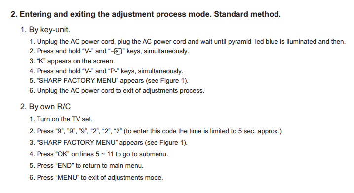
First thing to try is the service mode:
Well, nothing worked. As I learned later, I should have been more patient. But then, I started my routine checks instead.
Power supply
5V stand by: check
12V: check
5.75V: check
BL_ON (backlight): low, means off
Aha, so the processor didn't switch the backlight on. As this TV has no diagnostic blink codes, this meant testing all the voltages:
I noticed that IC3701, the frame rate converter (FRC) was running too cold. This thing should heat up. That was suspicious.
All voltages checked out good. The FRC chip had all required voltages.
So on to the TCON board:
The supply voltage was missing! Where did it come from? On the main board there is a little control circuit with a FET, which switches the supply.
And guess where the control signal PANEL_ON_P1 comes from? The FRC chip! The chip has an EEPROM connected to it:
I took my scope and probed the EEPROM. Besides a short flash of activity on the clock line shortly after power on, there was nothing going on. I also tried the freezing trick I learned from norcal715 (my favorite repair channel) on YouTube with no luck. Did this mean that the FRC chip was dead? Oh dear.
In some desperation I browsed the net and came across a video I had already seen once. It is from Grand Pass TV Repair, another of my favorite channels. The guy is wrestling with a Sharp TV, which would wake up in service mode, but fail again after pulling the plug.
https://www.youtube.com/watch?v=fBWX34wTULw
I gave the service mode another try. After about 10 attempts, the TV suddenly woke up and I was able to enter the menu! It's quite nasty. The trick with the buttons won't work immediately, it takes a number of tries. With the remote it won't work at all. I was fooled big time when I first attempted this. :-( Could have saved me a lot of effort. That's my personal Sharp lesson.
So, I went to the ETC menu and tried "EEP Clear" and "EEP Clear B" to reset the non-volatile RAM (NVRAM). In both cases, the TV went black and switched off. However, it still would not turn on again properly.
Pressing END during the factory menu opened the standard menu. It worked totally normal. There was nothing physically wrong with this set. Pressing the stand-by button on the remote switched it to stand-by ok (red indicator). But still it would not start up again.
A factory reset did not help, so I finally decided to run a firmware update, now that I knew how to start up the set. And this finally fixed it!
Hallo Frau Johansson!
So what exactly was wrong with this TV in the first place? No idea. The software somehow bricked itself. Luckily, there were ways to unbrick it, in contrast to the silly little Sony I tried to revive earlier this year.
This is a nice TV. The colors are good. The blacks are very dark. The sound is full thanks to the subwoofer. It may not have the fancy looks with its plastic case, but it has qualities!
I spotted some cheap capacitors on the power supply. They are all the same type, but one of them looked different. It is not easy to see on the image (the little, standing ones).
Desoldering is a breeze with my brand new pride and joy, the ERSA i-Con soldering station. This device is just awesome. Soldering is smooth like cutting through butter with a hot knife.
The 2x40 watts chip-tool makes desoldering a snap:
The left one looked slightly more bulged:
The capacitance values measured ok. The ESR was not really exciting but the caps measured different. The indispensable Blue ESR Meter in action.
For what reason ever, they are 47µ 50V, even though the maximum voltage there is 12V. I swapped them with some decent Nichicon HD 100µ 25V.
Ok, this TV is now ready to run just fine for a couple of years!
The seller of this TV said that it suddenly failed and wouldn't start anymore. It was purchased early 2013. A bad capacitor was not likely. A panel failure just maybe. I suspected some failed semiconductor.
When I plugged in, the indicator light went blue. Nothing else happened. After about a minute it switched off. The power button on the TV would turn it blue for a longer while, but still nothing on the screen. The remote had no effect at all. The device did not go to stand-by, where the indicator would light up red.
Ok, I fetched the service manual from elektrotanya.com and opened it up:
First thing to try is the service mode:
Well, nothing worked. As I learned later, I should have been more patient. But then, I started my routine checks instead.
Power supply
5V stand by: check
12V: check
5.75V: check
BL_ON (backlight): low, means off
Aha, so the processor didn't switch the backlight on. As this TV has no diagnostic blink codes, this meant testing all the voltages:
I noticed that IC3701, the frame rate converter (FRC) was running too cold. This thing should heat up. That was suspicious.
All voltages checked out good. The FRC chip had all required voltages.
So on to the TCON board:
And guess where the control signal PANEL_ON_P1 comes from? The FRC chip! The chip has an EEPROM connected to it:
In some desperation I browsed the net and came across a video I had already seen once. It is from Grand Pass TV Repair, another of my favorite channels. The guy is wrestling with a Sharp TV, which would wake up in service mode, but fail again after pulling the plug.
https://www.youtube.com/watch?v=fBWX34wTULw
I gave the service mode another try. After about 10 attempts, the TV suddenly woke up and I was able to enter the menu! It's quite nasty. The trick with the buttons won't work immediately, it takes a number of tries. With the remote it won't work at all. I was fooled big time when I first attempted this. :-( Could have saved me a lot of effort. That's my personal Sharp lesson.
So, I went to the ETC menu and tried "EEP Clear" and "EEP Clear B" to reset the non-volatile RAM (NVRAM). In both cases, the TV went black and switched off. However, it still would not turn on again properly.
Pressing END during the factory menu opened the standard menu. It worked totally normal. There was nothing physically wrong with this set. Pressing the stand-by button on the remote switched it to stand-by ok (red indicator). But still it would not start up again.
A factory reset did not help, so I finally decided to run a firmware update, now that I knew how to start up the set. And this finally fixed it!
Hallo Frau Johansson!
So what exactly was wrong with this TV in the first place? No idea. The software somehow bricked itself. Luckily, there were ways to unbrick it, in contrast to the silly little Sony I tried to revive earlier this year.
This is a nice TV. The colors are good. The blacks are very dark. The sound is full thanks to the subwoofer. It may not have the fancy looks with its plastic case, but it has qualities!
Desoldering is a breeze with my brand new pride and joy, the ERSA i-Con soldering station. This device is just awesome. Soldering is smooth like cutting through butter with a hot knife.
The 2x40 watts chip-tool makes desoldering a snap:
The left one looked slightly more bulged:
2016-03-10
Philips 42PFL9803 - chassis Q529 - two blinks - shot FDS8884 FETs on main board - typical fault
The Philips 8000/9000 series from around 2010 are my favorites after the Panasonic NeoPlasmas. This one came in with the two blink code. The seller said it suddenly switched itself off and never came back alive.
Just look at this. Two fans and four decent speakers. Only one adhesive tape, the rest is done with clips. The power supply is built for eternity. Back in those days, TVs used to have a protective shield in front of the panel and the frame was rock solid. The golden age of LCD TVs.
Ok, service manual readily available at elektrotanya.com. The Philips manuals from those days are enormously detailed. They even explain the DC/DC regulator circuitry. Real engineering pride. They always give me good confidence to attempt any repair, even on board level. First thing to do with a dead Philips is to activate the SDM (service default mode). This is done by shorting the SDM point on the main board to ground:
The device will ignore a number of checks and keep running. Also, it will morse an extended error code via the stand-by LED. In my case it was 1 long - 8 short, which means code 18. Let's look it up:
Aha, so next task was to locate the DC supply circuitry on the main (SSB) board and measure. I found a broken fuse:
I measured the FETs right next to it and found 7U05 to be dead short. It was the 1.2V DC supply. All the FETs are FDS8884. Didn't have those in stock, but I had a number of FDS8880, which are from the same family, but can handle more current. After removing the FET I also did an A-B check on the two identical PWM chips on the underside and found nothing alarming. So the PWM chip could still be ok.
Now, for testing I connected a fuse holder with a 4A fuse and started the device. Klack klack - dead - blinking. The fuse blew again! Was I a little to hasty this time?
The FET was shorted again. Why? Because I was sloppy and did not properly check 7U06, which wasn't dead short but almost. This so-called 'lower FET' goes to ground and 7U05 goes to 12V plus. Therefore, this sucker killed my new FET by pulling it to ground.
Now this got me thinking again: if 7U05 goes short, which is connected to 12V and is feeding directly into the 1.2V line, 12 volts are hitting the processor! Even for a short period of time, this could be fatal for main processor's core. I also did some research on the net and that did not lift my spirits, either. In a number of forums I found a couple of similar cases with no good ending.
With mixed feelings, I replaced both FETs this time. I connected the board to my bench supply, limiting the current to 500mA. I first connected the 1.2V line directly and it only pulled much less than that. Chances were high that the processor was still good.
Then I connected the 12V feed. The DC/DC regulator came up ok and the board pulled a constant current around 550mA. Nice.
Back in the TV, I still kept the 12V feed connected to the bench supply. The TV wouldn't come up unless I raised the current limit to 1600mA.
This TV confirmed my opinion about the 8/9er series. Brilliant image! Totally even backlight, crisp colors, very high contrast. Like all LCD TVs I've seen, it does not match the natural colors of a Panasonic NeoPlasma. The viewing angle is a little critical, too. The colors quickly wash out viewed slightly from the top. Like many LED LCDs, it emphasizes reds a little. The software does offer a custom white balance, which does help somewhat.
The sound is powerful, homogeneous and spacey, thanks to four proper wide-band speakers.
I was lucky++. Later I found the following warning note in the manual:
And this:
These guys know their stuff!
I should have checked the FETs first. In my case, the fuse blew and they were inactive, anyway. But if they had produced over-voltage without blowing the fuse, I definitely would have fried the main processor. The main board is not available anywhere, not even in the most exotic countries.
Always fully read the fucking manuals!
As this TV had some mileage, I also had a look at the power supply's solder joints. None of them showed any signs of aging. As a precaution I re-soldered all FETs and diodes. All heavy and hot parts are mounted in rivets, the heat sinks are ridiculously over-sized. They get a little more than hand-warm at best.
A great machine. However, it seems to have trouble with the DC/DC stage sometimes and according to some voices on the net, it may fry its processor.
So what about the three blinks error code?
The same model was on eBay at the time, with a three blink error code. According to the manual, this means 12V supply failure. Your first instinct would focus on the power supply. But, from what I know now, I'd suspect an identical failure, albeit with no open fuse. The DC/DC stage might produce heavy over-voltage and there is nothing the protection circuitry can do about it except cutting the 12V supply. The warnings from the manual have to be taken very seriously. The question is: did the ICs survive the attack or not?
Just look at this. Two fans and four decent speakers. Only one adhesive tape, the rest is done with clips. The power supply is built for eternity. Back in those days, TVs used to have a protective shield in front of the panel and the frame was rock solid. The golden age of LCD TVs.
Ok, service manual readily available at elektrotanya.com. The Philips manuals from those days are enormously detailed. They even explain the DC/DC regulator circuitry. Real engineering pride. They always give me good confidence to attempt any repair, even on board level. First thing to do with a dead Philips is to activate the SDM (service default mode). This is done by shorting the SDM point on the main board to ground:
The device will ignore a number of checks and keep running. Also, it will morse an extended error code via the stand-by LED. In my case it was 1 long - 8 short, which means code 18. Let's look it up:
Aha, so next task was to locate the DC supply circuitry on the main (SSB) board and measure. I found a broken fuse:
I measured the FETs right next to it and found 7U05 to be dead short. It was the 1.2V DC supply. All the FETs are FDS8884. Didn't have those in stock, but I had a number of FDS8880, which are from the same family, but can handle more current. After removing the FET I also did an A-B check on the two identical PWM chips on the underside and found nothing alarming. So the PWM chip could still be ok.
Now, for testing I connected a fuse holder with a 4A fuse and started the device. Klack klack - dead - blinking. The fuse blew again! Was I a little to hasty this time?
The FET was shorted again. Why? Because I was sloppy and did not properly check 7U06, which wasn't dead short but almost. This so-called 'lower FET' goes to ground and 7U05 goes to 12V plus. Therefore, this sucker killed my new FET by pulling it to ground.
Now this got me thinking again: if 7U05 goes short, which is connected to 12V and is feeding directly into the 1.2V line, 12 volts are hitting the processor! Even for a short period of time, this could be fatal for main processor's core. I also did some research on the net and that did not lift my spirits, either. In a number of forums I found a couple of similar cases with no good ending.
With mixed feelings, I replaced both FETs this time. I connected the board to my bench supply, limiting the current to 500mA. I first connected the 1.2V line directly and it only pulled much less than that. Chances were high that the processor was still good.
Then I connected the 12V feed. The DC/DC regulator came up ok and the board pulled a constant current around 550mA. Nice.
Back in the TV, I still kept the 12V feed connected to the bench supply. The TV wouldn't come up unless I raised the current limit to 1600mA.
But that did the trick. It was working again! I was lucky. No ICs fried. A cheap repair.
Hallo Frau Johansson!
This TV confirmed my opinion about the 8/9er series. Brilliant image! Totally even backlight, crisp colors, very high contrast. Like all LCD TVs I've seen, it does not match the natural colors of a Panasonic NeoPlasma. The viewing angle is a little critical, too. The colors quickly wash out viewed slightly from the top. Like many LED LCDs, it emphasizes reds a little. The software does offer a custom white balance, which does help somewhat.
The sound is powerful, homogeneous and spacey, thanks to four proper wide-band speakers.
Epilogue
And this:
These guys know their stuff!
I should have checked the FETs first. In my case, the fuse blew and they were inactive, anyway. But if they had produced over-voltage without blowing the fuse, I definitely would have fried the main processor. The main board is not available anywhere, not even in the most exotic countries.
Always fully read the fucking manuals!
As this TV had some mileage, I also had a look at the power supply's solder joints. None of them showed any signs of aging. As a precaution I re-soldered all FETs and diodes. All heavy and hot parts are mounted in rivets, the heat sinks are ridiculously over-sized. They get a little more than hand-warm at best.
A great machine. However, it seems to have trouble with the DC/DC stage sometimes and according to some voices on the net, it may fry its processor.
So what about the three blinks error code?
The same model was on eBay at the time, with a three blink error code. According to the manual, this means 12V supply failure. Your first instinct would focus on the power supply. But, from what I know now, I'd suspect an identical failure, albeit with no open fuse. The DC/DC stage might produce heavy over-voltage and there is nothing the protection circuitry can do about it except cutting the 12V supply. The warnings from the manual have to be taken very seriously. The question is: did the ICs survive the attack or not?
Subscribe to:
Posts (Atom)