No commercial links

Sorry, I had to close comments due to permanent spam. Too much cleanup work.

2015-06-12

Toshiba 37RV635D - distorted picture - wrong model ID and panel ID in system configuration - update via USB fails

This was a fun repair and I have learned a lot from it. I picked up a Toshiba 37RV635D from eBay Classifieds for 45€. The owner said that all of a sudden the image got a yellowish tint. The images he provided showed a lot more than that. Weird image noise and color distortion.

So, when I started the TV at home with a program fed into HDMI, I got this:


Wow, this may go as modern art, but it's far from a good image :-)

Something on the main board is going very wrong, I thought. A TCON board cannot produce such images. There were no errors in the scanning. Everything was at its intended place on the screen, but the colors were all wrong and there was noise inside the shapes, especially where white areas were supposed to be.

Zooming into the image; interesting block structures:


The menu at close-up. The entries were still readable, so I was able to at least control the TV.


The image supplied by my Nexus 7 looked nowhere near the original:


Software Update Woes

At a couple of places I read that re-initializing the TV with a software update could sometimes straighten weird image distortions. So, I downloaded the latest firmware and put it on a USB stick, which I formatted with FAT (not FAT32) as required by Toshiba. 

The TV just wouldn't accept the data on the USB stick, even though the media player was able to navigate into it. I browsed through a number of forums and one guy recommended to format the stick with HP USB Disk Storage Format Tool.  I mean, really? Well, I tried that and it worked! No comment...

Alas, the update did not fix it.

Getting On

Even though I immediately suspected the main board, I started my standard routine checks. 


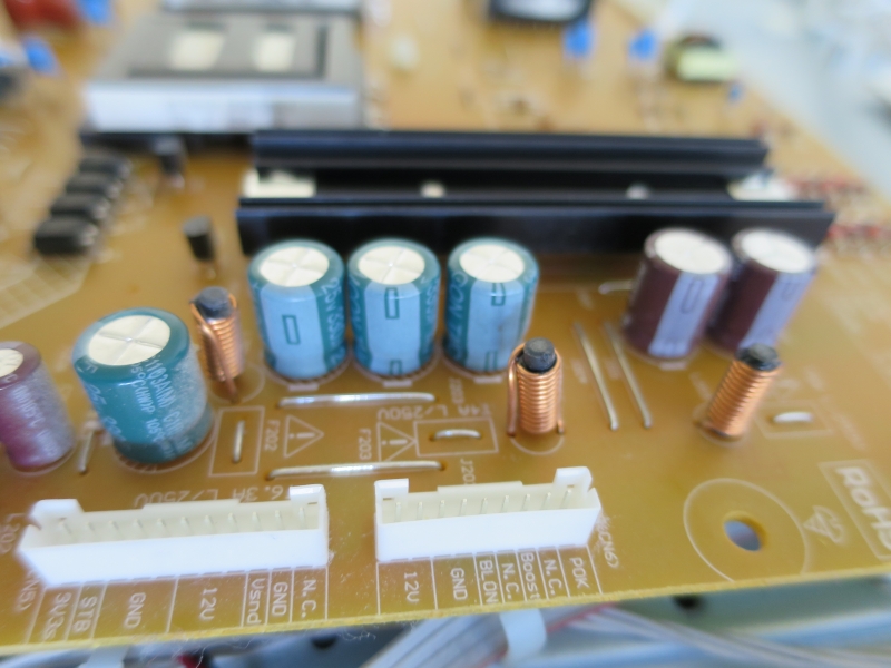
First, the power supply. Nothing caught my eye there and the caps measured all ok. Only top quality caps. Well done, Toshiba:


The 12V line measured a little low (11,7V) and was pretty noisy:


Well, that must have been the noisiest power supply I have seen so far, but it looked ok, nevertheless. All the regulated supplies on the main board were low noise and the voltages made sense.

Just when I looked up (and found) a replacement main board in my preferred sources, I remembered a repair story in Kent Liew's LCD TV Repair Tips 4.0, where he fixed a similar-looking problem by re-configuring a device via the service menu. It wasn't a Toshiba though, but I gave it a shot. The service manual is available from elektrotanya.com.

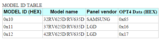
Among other things, the service manual describes how to configure the main board properly for the given TV type and panel type:
To switch the Toshiba into service mode, you do the following:
  • Press and release the mute button on the remote twice
  • Press and hold the mute button on the remote
  • Press the Menu button on the TV

All that in quick succession. A red S appears at the top right corner. In the left corner, the individual config settings are shown, which can be paged with the Program Up/Down buttons and modified with the Volume +/- buttons on the remote.

The SETID specifies the TV model. It was way off and complete nonsense! I set it to 11hex according to the model table:


Same thing with the panel ID. It was set to 65hex, which belongs to the 32 inch model with a Samsung panel. Mine is a 37inch with an LG panel!


After that, you press the "Info" button on the remote and the "Program Up" on the TV at the same time. The TV reconfigures itself and reboots.

Tadaaaa! The image was back!


Actually, I had to repeat the process because the IDs were wrong again. Not so bad as the first time, just off by 1. Why? I don't know.

How does that finding fit the description I got from the seller? Normally, I would conclude that someone who had no clue what he was doing swapped the main board with a used one from eBay or so, and got stuck. However, the TV looked untouched. Anyway, it was a cheap and quick repair!

About Toshiba Service Mauals

The manual I've downloaded from elektrotanya comes in a strange format. It consists of a large number of HTML files, images, and DWF files. Opening the start HTML page will complain "The ZEUS engine cannot be located". The manuals require the installation of the ZEUS engine, which is also avaliable as a RAR from elektrotanya. This software is very old (2007) and consist of JavaScript files of the most peculiar kind. The installer says that IE6(!) or higher is required. I couldn't get the thing to run on my W7 64Bit machine with chrome. Bummer!

Some HTML pages may work nevertheless. The setup I've described is located in !adj-sm.html, for example.

Now, what are those DWF files? They are Autodesk project files and contain the schematics and board layouts. Nice! You need to download the free reader program Autodesk Design Review.

When you open a file, you will see nothing. It took me a while to grasp the program. First, the WHITE_MASK in the Layers list must be switched off:


After that, you'll see something like this:


The red thingies are layers for each(!) individual component to indicate its location. That is enormously useful with complex boards like the main board:

But I cannot tell the wood from the trees anymore! Well, you need to switch off all the component layers and then you can zoom into the details as much as you like. To locate a component, just switch its layer on.

This is pretty darn good! I spent so much time searching for components in the vector graphics of the Philips manuals.

The layers which reveal the complete drawing are called:
  • 0
  • BLACK
  • GRAY
  • HOLE
  • MAGENTA

Unfortunately, some of them are right in between the components in the layer list, so it is a little tedious.

2015-06-08

Philips 40PFL9715K - 9 blinks TCON board defect - FDS8813NZ MOSFET failure

A friend of mine is a big Philips Ambilight fan and asked for a TV for his parents. I came across this Philips 40PFL9715K in eBay Classifieds and picked it up for 125€. The seller said that the image unpredictably goes black. A quick test at the seller's place did not show the error and the panel looked 100% ok. That's always the first thing I'd like to be sure of when I start a TV project.

I switched it on at home and - nothing but flickering. TV won't start. Weird. It must be a semi-mechanical problem then. The vibrations during transport already had some influence, obviously.

Also, a regular clicking noise was emitted from the TCON. Oh, I hate clicking TCON boards! With mixed feelings, I opened up the machine.


This device is packed! A sattelite receiver, built-in WiFi with one antenna on each side, two woofer speakers and an Ambilight which also illuminates the top of the TV, not just the sides. And, thank you Philips (or Toshiba, for that matter, who produced the panel and the TCON), the TCON is deeply buried under plenty of cables and the holder for the stand. I hate this!

As always, some tapes and cable guides were loose due to dried glue. And some sloppy wiring here and there. Philips is not Panasonic or Sony:


The "eyes" of the so-called woofers reminded me of something...


The first thing I do is to check the power supply voltages. They all measured exactly as it is printed on the board. Except for the 12V line driving the TCON, which is supposed to have 12.5V and only had 11.9V. I found some cheap arse electrolytics:


I removed all the green ones to measure them individually, but none of them had any defect. ESR and capacity were perfect. Anyway, let's use the opportunity and put some quality Nichicon HD in instead. I had to bulge the back cover a little to make room for the big one :-)


The voltage was still at 11.9V, so that was most likely ok and the 12.5V were never there in the first place. A little irritating still. A quick check for supply line noises neither showed anything to get concerned.

I removed the TCON and attached it to my bench power supply to investigate the click noise. This was the biggest TCON board I've seen so far.


It behaved weirdly. Besides the clicking noise, the current consumption flipped between 1.4A and 0.8A. The voltages measured ok, basically, but the one for the big processor wasn't stable and the PWM impulse at the MOSFET gates regularily dropped out for a tiny amount of time.

The processors get really hot and I had to interrupt the diagnose often to let everything cool down. As I mentioned earlier, I suspected a mechanical problem, so I squeezed and twisted the board at various places. Nothing had any effect until I pressed my finger on the FDS8813 MOSFET. The board immediately stabilized. I suspected a wildly chirping DC/DC converter chip first. To find the FET was actually a relief.

A bad solder joint? I reflowed both FETs. The clicking was gone and the jumps in supply current also.


Back in the device, the TCON board behaved well until I plugged in the LVDS cable. Then the clicking started again and the TV standby blinked 9 times, which indicates a non-responsive TCON.

Nevertheless, I was sure that I had found the reason for the defect. Those FETs were not completely dead, but once they got under load, they misbehaved.

I browsed eBay. A refurbished board cost 125€. Outch! But what's this? Someone who had the same problem offered the exact same FETs I had my hands on. Great! And only 10€!

Ordered, soldered in, TCON drew a constant 0.8A, TV worked :-)

Why did the FET(s) die? They run extremely hot. A little heat conducting block connects them to the cover. The two processors steaming along at over 70°C are close by and grill the two FETs. What a cheap and stupid construction, Toshiba! I decided to improve matters and glued a heatsink on top of the FETs. This brought down the temperature there to about 55°C. The horizontal orientation isn't ideal, but I had no choice here because of the flat cables below it.


Also, to improve convection, I drilled holes into the back cover right on top of the heatsink:


I hope my friend's parents will enjoy their TV for a long time.


Can this TV beat a Plasma's image quality? No. Even with its direct LED backlight. Like all of the LCD TVs I have repaired, apart from the Sony, it produces a harsh, a little unnatural image for my taste. I am constantly aware that I look at a TV image. With the Panasonic plasmas, I am able to forget that, immerse into the images and feel like looking into the world (with full HD material at least).

Nevertheless, the Philips gives a very decent performance. The picture is crips, and the sound is voluminous thanks to the extra "woofers". The image tint is too much in the red, which can be adjusted via the individual white balance. The 9er series also has a nice heavy aluminum-style remote with precise buttons, not the cheap wobbly plastic one that the lower series have.

Update


The TV did not last long. My friend had it running for half an hour and then it started rebooting again. Now it doesn't even start at all anymore. Argh! It's going back on the lab table. Let this not be one of the BGA chips, please!


It turned out that the FDS8813 was broken once more. I think I made a mistake during reassembly last time and the transparent plastic piece sneaked between the metal cover and the heat-conducting block for the MOSFET. It is exactly in line and reaches just on top of the chip :-( So, I effectively isolated the chip from its heatsink.

Four evenings intensive testing at over 30° celsius room temperature and it is still running fine. I guess it's fixed for good. :-)

Update 2


The FDS8813 ist the strongest member of the FDS88xx family. It is still resonably cheap and can replace all the other 8880 (the companion FET on this TCON), 8884, 8882 (on some Philips main boards). There is no need to keep the others on stock.

2015-06-01

Grundig Fine Arts 32 - strange backlight defect - not fixed, but hacked to make it usable

A friend wanted a 32 inch full HD to use as a PC monitor. Those are not easy to find. Most (defect) 32 models are 720p. I found a Grundig Fine Arts 32 on ebay and my friend got it for 42€.

If we only had investigated the seller a little more. It was a professional TV repair shop! Now, if such a guy gets rid of a TV, it will not be an easy fix. In fact, I wasn't able to locate the error this time, but at least I found a wild hack to make the TV usable.

Grundig is actually a no-name product. Someone in Turkey just slaps the name on the devices and the software on the mainboard gets some customizing. I found an almost identically looking TV under the name Murphy, which seems to be Indian. Apart from that, it is a pleasantly looking device with a very stable aluminum frame, a very heavy back cover and a solid glass foot. No plastic anywhere. Hovewer, you will not find any service documentation on those devices.

We needed luck.


When I switched it on, it was dark. With the help of a torch I was able to see the menu. So, the display worked fine. Always a relief.

Then I turned my attention to the inside and the inverter board in particular (the little board in the middle). The TCON and inverter board are part of the panel and manufactured by Samsung. The rest by god knows who.


This board is a nightmare to analyse. It is not just producing 95V for the LEDs, it also has a complex circuitry with a micro processor in the center, which controls the boost converter voltage and the LED dimming.

The next image shows the driver stage. There are four independent LED channels, each driven by a transistor. The transistors control the ground level of the LEDs. The 95V go straight into the LEDs.


I noticed that one of the transistors had a different voltage on its base than the others. This could not be ok and I traced the problem back to a quad OPA, which controls the base voltage of the transistors. Ok, a standard part for 25 cents. I soldered in a new one and was bitterly disappointed that nothing had changed, even though the transistor now was in line with the other three.

Countless hours of testing and experimenting followed. I tested the LEDs with my high voltage bench power supply and all four channels were perfectly ok. Continuously dimmable with no excess current. The 24V supply to the board was stable and the dimming voltage signal from the mainboard was in sync with the menu. Thus, all the inputs were ok. I couldn't say much about that mysterious "sync" input from the TCON, which is supposed to control the adaptive backlight (my theory) and exposed a regular square wave pattern at 150Hz. Whatever this does...disconnecting it did not provoke anything at all.

It turned out that the backlight had only two states: fully lit or completely off. The backlight intensity control menu goes from 0 to 100. At 41, the light snapped from dead to full, but not above 41, no, below 41! That didn't make any sense at all.

I suspected the microprocessor. It is actually cheap, but changing it was no option, because its built-in EEPROM contains the control software.

I came to the conclusion that this board is doomed and ordered a used one from flattvparts.co.uk. Alas, that board exhibited the same erratic behavior. Well, sometimes used boards are defect, so yet another one was ordered from eBay. No luck! Still not working! Both boards came from professional sellers, so I have the chance to send them back.

Desperation was creeping up.

While poking around on the board with my multi-meter, I noticed that the backlight would come on once I touched a certain trace, which lead to the processor. What the..? The processor input is connected to the dimming signal from the main board through two transistors. It knows only two states: High or low. Aha! Pulling it low for a tiny amount of time - the capacitance of the multi-meter was enough - fired up the dimming logic.

Screw all this. I decided to connect a simple "pull down starter switch" as a hack to make the TV at least usable. No backlight dimming, always 100%, but a cheap semi-fix.


Well, this hack works reliably :-) Switch the TV on, wait until the stand by LED stops blinking, press the button, enjoy a fully lit image.

How the circuit on the inverter board is able to dim the LEDs in a continuous fashion is beyond me. The input circuitry, which handles the dimming voltage from the mainboard, switches hard between high and low. I could not find any other pin on the processor, which is coupled to the dimming signal. The only possible input left is the sync signal from the TCON. But this doesn't change with the dimming and is constant. Maybe it was the TCON all along? But the image is perfectly ok, and I did not want to take any chances there.

My nerves were put to a test this time, and the TV is not actually fixed, but I am still satisfied that I came up with a workable solution.

2015-05-23

Panasonic TX-P50GT30E. Once more the 7 blink disease - TNPA 5335 scan/sustain board fixed cheaply.

When I saw a 7 blink Panasonic GT30 in eBay classifieds (Kleinanzeigen), I acted immediately. I've learned how to fix this standard problem of the 30 series with my 42ST30 and this one was bigger and the better G-type. The S-type is the budget version. The G improves on the S as follows:

  • DLNA
  • SAT receiver
  • USB recording
  • Improved contrast filter
  • Much finer image adjustment options. Two expert modes and a THX mode.
So I picked it up for 200€. A quick measurement revealed the usual. Loose screws and 6 transistors plus 2 diodes shot. This time I found a cheaper repair kit for the TNPA 5335 board from Germany for 40€.

Let's have a look. The next image makes me go wow! Just wow! Panasonic Plasmas are magnificent machines, meticulously built. It's a pleasure to study the attention to detail. If Panasonic just wouldn't have, well, screwed up the screws.


In the 50 inch model, the buffer boards are separated from the sustain boards, which makes maintenance a lot easier. The panel connectors can stay seated. As I reported here, those are not easy to handle.


I examined the screw holes and their contact area. This did not look good. I think we see black traces of sparking here:

The next image shows the damaged semiconductors. It was not as bad as with the 42 inch. No ICs and small signal transistors affected, just the big thingies. Neither had the power supply failed. I think, in this model, the engineers paid more attention to protection circuits.


Here we go again. Pre-heater plate and hot air makes replacing the parts a smooth operation:


The TV started up no problem after the repair.

The 50GT30 is a brilliant TV. The images are stunningly beautiful. The 3D performance is second to none. Crystal clear. It feels like looking through a window into the world. No other TV I've put my hands on comes even close.

The sound is bad, though. A lot is missing in the highs and there is too much fat in the midrange. I don't care much, as I have my stereo to the left and right of the screen.

A TV as gorgeous as Scarlett Johansson :-) Nothing beats a Plasma when it comes to skin tone.


Watching Gravity in 3D is breathtaking:


Plasmas have a natural sharpness, which LCDs just don't seem to achieve without tricks. The plasmas don't have the funny lock-in effect on hair, when suddenly the shimmering, silvery reflections stand out once a person stands still.

Well, I'm afraid my beloved Sony, which is my first TV repair must trade places with my new darling :-)

It still puzzles me that the screws are the reason for the defect. Their material is very soft. The screwdriver wears them out quickly. Maybe they stretch too much. Or the solder they sit on flows and that loosens the screws. This would be a silly engineering mistake. However, some screws are mounted on a solid bracket and those were still sitting tight. So maybe the engineers underestimated the importance of the problem screws.

2015-05-17

LG 37LH7000 - LVDS and panel connector contact problems and TCON board defect

Every TV repair is like a journey into the unknown. It's just never boring.

A friend asked me to find her a not too big TV and I got a LG 37LH7000 for 45€ on eBay. The seller said it had green stripes across the screen. The photo on eBay wasn't very clear but I was confident that it could not be a defect in the panel, and everything else is fixable.

When I switched it on at home, I got this:


Damned! This very much looked  like a panel failure, because it had horizontal lines in it, and a rule of thumb of mine says that for horizontal structures the panel is very likely to blame. However, the vertical unregular blocks indicated a TCON problem.

I also heard a dzzzzzzt, dzzzzzt buzzing sound from the back in regular intervals. The small horizontal white noise band at the top of the screen reacted to activity on the menu button. A good sign. So there was a signal arriving at the TCON and from there on it wasn't processed properly.

First rule of TV repair: don't give up too quick.

I first wiggled the panel and applied pressure to the frame at various positions. Sometimes, the thermally bonded connections to the panel go bad and external pressure can make them work again. Not here, though.

I then removed the panel connectors and LVDS connectors, applied contact spray to them, re-seated everything, and the image was back - almost:


The buzzing was still there and corresponded perfectly with a regularly appearing noise pattern, which you can see at the top. I then fiddled with one of the TCON connectors some more and the TV seemed to work flawlessly that evening and I celebrated my cheap repair. The next day I switched it on and the noise pattern was back.

It was time to dig into the TCON board. I noticed that the buzzing sound won't disappear once the panel was disconnected. Good news again, because the panel could finally be ruled out as the problem maker.

I poked around on the board with my scope to find something which correlates with the noise pattern. I found that the positive charge pump of the TPS65161 DC/DC chip, which provides all voltages for the panel, was dropping out exactly in the same interval as the noise appeared. A clicking sound on the board accompanied each drop-out.


This is what a good charge pump output looks like:


My repair journey became a little strenuous and frustrating then. I first replaced the TPS chip, because it's dirt cheap (3€). That didn't improve things. Then I unsoldered the ceramic caps, which smooth the charge pulses. One measured a little strange, but testing the board with an electrolytic cap instead neither improved the situation. All diodes and transistors measured ok.

Close up of the TPS65161:


I then unsoldered a zero ohm resistor, which was conveniently placed - presumably as a fuse - in series with the charge pump's output. This made an easy current measurement possible. Measuring currents on a tightly packed SMD board is a very difficult task, which can not be performed without destructively cutting microscopic traces. I like to avoid that as long as possible.
There were 60mA flowing until the pump dropped out. According to the data sheet this was already too much, and the panel had not even been connected, yet! Something was drawing excess current on the TCON. At that point I gave up, because this discovery pointed towards the big processor chip.

I ordered a new board from flattvparts.co.uk (excellent shop, by the way) for 50€ including shipping.

The new board measured ok without drop-outs, but the regular noise pattern was still there! What the...!! In a mild rush of desperation I used a glass fiber pen to polish the LVDS connector once again, this time also at the mainboard, where they were literally baked to the socket and went loose with a snap. Well, some of the gold plating is gone now, but what the heck. I applied silicon grease to help it against corrosion, a trick I saw in a youtube video by @norcal.

A glass fiber pen is actually a little too abrasive for delicate contacts:


In his book LCD Repair Tips 4.0, Kent Liew mentioned using an eraser to polish the LVDS connector. I did not have any suitable eraser at hand (who still uses pencils these days...). I think I'll stay with the glass fiber pen. Used gently, it is able to polish contacts without removing too much material.

The TV is stable now. It feels a little unfinished, because I'd rather be able to say "this part was broken" instead of  "this contact should work now".

I've learned a lot from this journey. A bad LVDS contact, which is not detectable even under a 10x magnifier glass, and won't go away even with the best contact spray, can produce the wildest phenomenon on a screen. And it most likely killed the TCON board with the intermittent pulses that resulted from it.

About the device and the service manual

The device's build quality is mixed. The boards contain Japanese quality caps. I measured the ESR of all caps on the power supply and they were perfect. The ones on the main board, which I could reach, were also in good condition. The frame is solid and the HDMI ports are screwed to the back cover.

On the other hand, the wiring is sloppy like in many brands, besides Sony and Panasonic. After 5+ years, the tape glue fails and everything starts falling off. It looked like a mess in there.

The service manual has scalable schematics of the main board. The power board, inverter board and TCON (as always) are missing.

Update

Oh boy, this TV kept me busy! After two weeks the funny lines on top appeared again and my friend even reported temporary "split screen". As it turned out, the LVDS cable was to blame. One of the contact traces had lost a little piece. I fiddled in a spare cable and since then it is working ok again. Let's see for how long. I also took the opportunity to completely tear apart the panel. I cleaned the diffusor plate, which had accumulated dust. This had shown as dark bands and blotches in the image.

Update 2

This thing is driving me nuts!! After it had worked flawlessly for a week, I moved it aside for a while and didn't use it. When I switched it back on, the noise patterns appeared. This is a total mystery. It seems as if something is going bad when it is not used. Normally, that would be capacitors. I measured all of them without findings. All voltages are good. Neither could I find anything in the LVDS signal, which correlates with the noise. I think I'll give up on it.

Update 3

I bought another defect set of the same type in hope to swap boards. Alas, the second TV had the same fault :-( It turns out that the only factor was the running time. All the things I did had no correlation to the actual fault. The more I worked on the thing, the better it would run. I swapped the main and TCON with no success. It must have been a scan driver error in the panel.

Screw that, I removed all the boards from both sets and the rest went into the trash.

2015-04-28

Panasonic TX-P42ST30E - TNPA5330 board defect - seven blinks and six blinks of death

The Panasonic Plasma 30 series (ST30, GT30, VT30) all suffer from a very silly bug: the ground screws of the SN (scan + buffer board) go loose and eventually produce sparks, which will kill a whole bunch of semi-conductors on the SN board and probably on the power supply board, too.

(In the meantime, I have analyzed this defect in more detail HERE)

The symptoms are 7 or 6 blinks of the standby LED. The service manual says:


A new SN board is prohibitively expensive. I did not find any under 230€ on eBay. In other models, Panasonic used to split the buffer board from the scan board. Here though, it is all in one and the buffers make it so expensive.

Luckily, there are repair kits on eBay tailored for this problem. I got one from GTV Watford in Great Britain. Including shipping it cost me 83€. The TV itself  was only 45€.

The following image shows the shot parts on the TNPA5330 SN board. The red marks are the parts covered by the repair kit, the yellow mark is a transistor, which is not included in the repair kit.


That's not all. Due to the diodes and transistors going short on the SN board, the power supply board blew a fuse and two FETs also died. See next image. For this, GTV offers another repair kit.


My brand new pre-heating plate and hot air gun finally got something to work on:


I covered the capacitors with capton tape and heated the board up to around 140°C. With the hot air gun set to 420°C the SMD-mounted large semi-conductors came off quickly and without a problem. For soldering, I used solder paste and the same temperature settings. It is fun to see the big thingies snap into place once the paste has reached its melting point.


Replacing the fuse and the FETs on the power supply:


After replacing the large diodes and transistors, I ran a test and still got 7 blinks. So I fitted the remaining two parts from the kit also. They are a switcher IC and a double transistor. This pair occurs in all four energy recovery or sustain circuits, respectively.


After I had used all the parts from the repair kit, the TV ran fine for a couple of minutes and then suddenly switched off again, this time with 6 blinks instead of 7 blinks! What was going on?

I checked all the scan and energy recovery circuits again and lo and behold, I found Q451 with a short between Gate and Collector. It is part of the RECOVERY-L section. Apparently, it had been already pre-damaged and finally broke during my first test run.


This particular transistor was not supplied by the repair kit. In foresight, I had ordered a working SS-Board on eBay, which is the little sister of the SN board and contains most of the same semi-conductors except for the expensive buffer chips. The SS boards are cheap. Mine was 30€. The SS board had two DG302 transistors on it and so I picked one from there.

In hindsight, it would have been cheaper to order two SS boards, which I think would cover even more than the necessary parts, instead of the repair kit.

This is what it looks like when one of the panel connectors is not seated properly. Thin horizontal lines all over the screen (the boxes are from the screen menu).


Those connectors are not so easy to seat. It takes some practice and I recommend using a magnifier glass to check that the little notches on the connectors are actually all the way in.

And now the Plasma does what it can do best: producing rich and beautiful colors:


It was quite some work this time:


To help with cooling, I glued small heatsinks on the large semiconductors and buffer chips. The heatsinks are not very powerful, but better than nothing at all. There is no space for large heatsinks, anyway.


A few words about the Panasonic service manual. The images for the boards and circuits are too small and not zoomable vector graphics and you can't see any of the small labels properly. Repairing a mainboard with this material is practically hopeless. The SN board is relatively simple and it did not matter. A mainboard is much more complex and you need all the fine details. Maybe there are copies around with better quality. I for sure did not find any.

The manuals from Sony and Philips which I have are much better. Personally, I would refrain from buying a defect Panasonic with a potential mainboard or logic board problem.

This TV is a keeper. It is missing DNLA features, but I will rather buy one of those Android quad-core devices with WiFi and HDMI, which have better performance and software on board than any of the Smart TVs out there.

Don't forget to improve the screws, folks! Replace the originals with new, longer screws with spring washers. Otherwise the same disaster might happen again.