No commercial links

Sorry, I had to close comments due to permanent spam. Too much cleanup work.

2016-12-30

How to test Panasonic plasma TV IGBT transistors - GT30F131 and similar, RJP30H2A, DG302

In Panasonic Plasma TVs the Y-Sus (aka SC/SN) and Z-Sus (aka SS) boards contain a number of high current, high voltage IGBT transistors of different types. Those are not easy to test, because they are hybrids. They have a MOSFET gate, but a bipolar emitter and collector.

The usual FET testing technique is to pre-charge the gate, not touch it again and then measure the source-drain resistance, which must be low with a charged gate. That doesn't work with IGBTs. Neither does the classic bipolar testing method work.

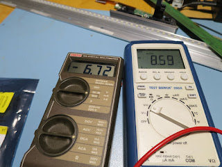
To properly test IGBTs, we need a test fixture. This circuit simply applies a variable voltage to the gate and the emitter-collector current goes through a resistor. We measure the gate voltage and the E-C current.


This battery-driven version is good for quick testing. To make comparisons between different devices and to put some stress on them, use a lab supply and decrease the collector resistor.


To test the SMD IGBTs I quickly solder the gate and the emitter to the board. The collector is connected to the tab and a gentle push on top of the device connects it to the large pad.


Now let's check the three types.

The 30F131 starts opening at slightly under 4V GE (gate-emitter) voltage. It is open at 5V.


The DG302 starts opening just above 5V, it is open at about 5.8V.


The RJP30H2A starts opening at about 4.2V and is open at 5V.


As you can already see, those IGBTs have quite different characteristics.

I spent a considerable time studying the offers on Aliexpress. Some were easily detectable as fakes. When the character font used for labeling is obviously wrong, the numbers are not engraved into the casing or the stamp in the center is missing or different, it must be fake. The pictures of the seller I ordered from seemed ok. Either they were more careful faking it or I get lucky :-)

I have a pending delivery of the 30F131 and RJP from China. I am going to check against fake devices with this test technique. The tests above have been conducted with original parts. I always keep some originals as a reference.

Update: Fake IGBTs

The RJP from China are obviously fake. Neither do the look the same, nor do they measure like the original. I will not bother using them to avoid further damage to the board.

Don't buy them from "Chinese Super Electronic market". I recon, to get originals you will have to spend a few dollars per piece.

The F131 don't look the same, but they behaved ok in the measurements. I am still not confident to use them.

I also ordered the driver transistors (SMD 3Y) and the control chip from that seller. I'll test those later.

I've put the fake transistors under the microscope. Please see this blog post.

C-E Reverse Break-Through Voltage Test

Another very revealing test is to measure the reverse break-through voltage between emitter and collector. I use my DUOYI DY294 tester for this.
  • The orginial RJP has 230V. The chinese fake only 45V(!!). I'll dump that garbage right into the trash.
  • The original F131 has 110V, so does the chinese. Maybe those are not so fake.
  • The original RF1501 diode has 375V, the chinese is right on the spot. Forward voltage is identical, too. So, those are most likely legit. They also look absolutely identical.

RF1501 diode is ok


In the meantime I fixed another 50GT30 with one of the RF diodes and they are working flawlessly. I can recommend the source for those.
https://www.aliexpress.com/item/10PCS-RF1501-RF1501NS3S-TO-263/32515394351.html

Sony KDL-50W685A - no image - panel fault

A friend found this Sony in eBay classifieds. The seller said that there was no image. Well, knowing about the LED problems in latest TV models, I suggested to give it a shot.

I learned from that journey that I will stop recommending Sony TVs. It was appalling.

First of all, this thing is built like a child's toy. A number of screws and clipped plastic parts. The variety of screw types is ridiculous. Conducting tapes slapped across parts. Hidden screws under tapes or wires. The whole device is built in a stacked manner, from the panel to the back cover. Easy to do in this direction, but in reverse it is a fucking nightmare.


When we switched the TV on, it became clear quickly, that the LEDs were not the problem. From a thread in the IWENZO forum I knew about trouble with the TCON and panel, respectively. I headed straight to the TCON, which is integrated into the boards, which are connected to the panel via bonding.

I quickly found that all the Gamma voltages were missing. The voltage regulators worked ok.
Here you see the actual TCON board: it is combined with the right side's COF drivers. It is irreplaceable.


I got a bad feeling. Next, I disconnected the left side of the panel from the TCON. In the next image you see the connecting flat cable between the right side and the left side.


And we got half an image! Damned. This panel was dead.


I measured all the components on the left board with no findings. Before I go and dismantle a TV I like to be 100% sure. After bending the panel a little, a stripe appeared on the disconnected, white side. That settled it. A broken source driver.


It might have been one of those COF chips, however I did not find anything suspicious visually.


I tore the panel apart and to my surprise I found an edge-lit LED design. So that panel will not have so much trouble with LEDs, they are mounted on a proper piece of aluminum, but it seems the left side dies a lot.


On eBay there are surprisingly many LED driver boards on sale. I mean, come on, this model is just three years old! Obviously, they die like flies and I believe it is the AUO panels.

If all newer Sonys are built like this, I must call them junk. When there is even no chance to swap a TCON and panels die after three years, Sony is dead to me.

What can you still buy these days and hope for seven or more years of solid performance? I don't know. Panasonics maybe, but due to the price pressure, even Pana may not be able to do magic. People want everything cheap and therefore we dump TVs at least every four years because they won't last longer. This is a shame! I am also a little sad, because repairing TVs will not be such fun anymore in five years time.

2016-12-17

Grundig 32VLE5303 - 3 dead LEDs

A friend brought me his mom's TV. It did not show any picture, but sound was ok. The first test in "no picture" situations is to take a flashlight and shine it on the screen. The image was there, so it had to be a backlight problem.

The 25V for the inverter checked ok and stable. After dismantling the panel I pulled out my LED backlight tester. And this was the result, three LEDs on the top were dead. Most likely the heat is accumulating at the top and those die first.


In this model, the inverter is mounted inside the panel.


I asked for help in the IWENZO Forum and a member sent me 10 LEDs. Thank's Jens! In the meantime I ordered a sack full of LEDs from Aliexpress.

I used a spatula to remove the strips from the panel. They were glued with adhesive tape, whose glue was hardened already.


To test a single strip, use the test points at the socket end. The polarity is printed next to them.


The plastic lenses had to be removed forcefully. They had been melted onto three black plastic pins.

The first surprise was that the replacement LED had cathode and anode swapped. The large pad was the anode. So the large pad on the LED had to fit on the small pad on the strip, which moved the LED out of the original center.


This is way too much solder paste, by the way. I shorted the LED out with that. Half of the amount is just right.


I soldered the LEDs with 370°C hot air.  This turned out to be a good compromise between speed and melting the LED lens. Using the iron was impossible due to the pad swapping. The small pad on the strip just was not reachable anymore. You will see the LED start floating once the solder is melted. It is a pretty easy and clean job.

Testing the new LED:


Testing the backlight again:


At the first attempt, I did not take much care about the lenses. I centered them on the LEDs and glued them with plastic glue. The result was this:


Ugly clouding! Why was that? The lenses have to sit perfectly perpendicular on the strip. Once they are skewed a little, their light beam doesn't hit the diffuser plate in a 90° angle anymore.

So I removed the lenses once again and used a file to make the pins on which they rest perfectly flat. The black pins on the strip got the same treatment. They were uneven due to the hot air and forceful removal of the lens.


Now this looked much better:


The clouds are almost gone. You could still see the new LEDs, which are brighter and more blueish, but that wouldn't be noticeable with normal images.

Her cuteness Juno Temple was happy to test the new backlight.


The backlight intensity was set to 100. I turned it down to 70 to prolong the life of the remaining LEDs. I strongly recommend to reduce the backlight intensity on LED TVs if possible! The most common fault of modern TVs (2013 and up) are faulty LEDs. The panels are constructed so sloppily (on purpose?) that a failure is inevitable.

It is ridiculous, if you think about it. LEDs replaced the CCFL tubes not only for economical reasons, but they also promised a longer life. The older Philips models for example proved that right, I have yet to see one with a failed LED, but the latest rubbish panels from LG and Samsung turned it upside down.

If the term planned obsolescence applies to TVs, the backlight would be my candidate. All other defects I've seen so far may be attributed to a lack of careful engineering, but those direct-lit LED backlights are around for over three years now, they die like flies and nothing has changed.

About LEDs

I have used this type: UNI LED
Problems: they have an opposite polarity and they are a little too big. They are more blue and shine a little brighter. I cannot tell for sure whether that is due to the aging of the original LEDs, but I assume not.

I think this type: JUFEI LED fits better. It has exactly the right size and the polarity matches. Due to its slightly higher forward voltage I assume it would shine darker. 

I am going to keep various types with both polarities on stock. They are cheap after all.

Philips 42PFL9803 - Q529.1 LE - flickering image - TCON defect - 1.8V regulator U5 EC50117

This is my first TCON board repair story. This Philips came in with a flickering image. It went completely dark a few times per second.

This video I got from the seller. I suspected a main board problem, it did not look like the panel was faulty.


When the image was visible, it presented very interesting patterns.


Let's analyse this quickly:

  • There are random pixels scattered across bounded areas
  • Some pixels are at the wrong place (the letters in the first image)
  • The panel loses its complete image and goes dark. Some supply voltage might be dropping regularly.

This wasn't a panel fault case as there were no stationary faults. The faults varied with the image structure. The menu generated different distortions than the static from the missing TV signal. Such noise can only be produced by the main board or the TCON.

As it was a lot easier to swap the main and I had one working spare at hand, I tried that first. No change. Then I swapped the also easily accessible dimming board, through which the signal is routed to the TCON. No change either.

Damned, so I really had to go through the tedious work of uncovering the TCON. It is buried under the sub-frame on which all other boards live. My standard routine to make sure that the panel is not to blame is to unplug each one of the flat cables to the panel. That did not show any static faults in the panel like it would do if address or source drivers were broken. And it still flickered.

The TCON was faulty! I checked all the voltage testpoints I could find, including the gamma voltages of the infamous AS15 chip. The VCC_S and VCC_M where unstable. They should be 3.3V but they swung about 400mV down in pretty much the rhythm that the panel was going blank. I knew I was onto something here. The TCON has two big chips, which are supplied identically. I did not assume that both chips were faulty, instead there had to be a common source of the problem.

I think VCC_S/M are provided by the big chips. The actual 3.3V regulator was absolutely stable.


And I found it. Surprisingly it was the 1.8V LDO regulator for the big chip's core, which was swinging in the same cadence. I think it rebooted the chips all the time and crashed the RAMs, too.


This little sucker is an EC50177 B. It is impossible to get in the TO-252 packaging, not even from Aliexpress. The alternatives in TO-252 I found did not deliver the required 1A.

But before I ordered some spare regulators, I wanted to make sure that this was the only fault. I removed the chip (and broke it to pieces while doing that...) and attached my lab supply. Hooray, the VCC line was rock solid again! The chips pulled around 0.622 amps without glitches.


Now I just had to see the TCON working with the panel attached.


And look at that! A flawless picture :-)

The only 1.8V fixed voltage reg I found from a local source (not Aliexpress again, please!) were LD1086 in the TO-220 package. Fair enough, there was plenty of free space and they are slim enough. And they can deliver 1.5A current. I'd work something out. So I ordered 3pcs from eBay for 7€.

The TO-220 package needed some modifications. I snipped off the tab and bent the legs. With some care it fit perfectly well. I also put a cooling pad on top of it so that it has contact to the cover.


TV working fine. Hallo Frau Green!


This model is built like a tank. It is very heavy, almost impossible to topple over, and the screen is protected by an extra layer of plastic. The ideal device for families with children where things sometimes fly around in the living room

2016-12-10

Philips 46PFL5507 - Q552.4E - DPS130 - dead stand-by - shorted ceramic C910 - open resistor R915 - dead chips DDA010, ST9M101

This Philips did not do anything once plugged in. Not even the stand-by light was on. That's a pretty clear indication of a broken standby supply. I could not measure any voltages coming out of the power supply and quickly concentrated on debugging the stand by circuit.

That was pretty tough. I found out that the PWM chip did not have its required VCC activation voltage. The reason for that was the open 2.2 Ohm fuse resistor R915, which is connected directly to the main capacitor's V+. The diodes all measured ok. The PWM chip had no short, neither had the line, which the resistor was connected to, so I soldered in a 2.2 Ohm resistor to check.


Booom! It took a fraction of a second to kill the new resistor. How is that possible? There was no measurable short and neither did I find any burn marks anywhere.

After some intensive research, I found a schematic in a Russian forum thread, which fit my power supply model DPS-130 well enough. The only component left, which could cause a short, was the capacitor C910. A 1kV 22pF thingy, which did not look suspicious at all. I unsoldered it and voilĂ ! No reading. It was dead, but not with a measurable short. My DY294 transistor tester confirmed the high voltage instability. Amazing how it did survive without any burn marks.

For a quick and dirty test I replaced the cap with a 4kV 33pF and the open resistor again. Supply not working. At least the short was fixed. Thus, the PWM chip must be broken, too. It still did not charge the starter capacitor (which tested ok, by the way) with Vcc. It is responsible for starting itself up once V+ is present at its drain pin. After the startup phase, it would feed itself through a secondary winding in the transformer.

I ordered 22pF 4kV caps via eBay and DDA010 chips via AliExpress. Three weeks later, the DDA010 arrived. I swapped it and the 22pF cap. Supply still not working. The PWM chip did not build up its Vcc startup voltage. I measured again. There was a constant 100 Ohms against ground on the Vcc rail. Under those circumstances, the starter capacitor cannot charge!

The only suspicious part left was IC902, an ST9M101. The original is impossible to find. The alternative part number is Infinno IM1M101-T6G. The documentation of this chip is ridiculous. It is used to sense the presence of the high input voltage. It can disable the PWM chip.


A jumper wire was conveniently located between the PWM VCC line and IC902. I opened it up and finally, the PWM chip was starting. However, it rebooted in a loop. IC902 was definitely defect, too (or maybe the PWM chip had not been dead in the first place). IC902 is also connected to the FB (feedback) line of the PWM chip and I assumed it was causing some trouble there, too.

Ok, another order from Aliexpress. On eBay there are repair kits available with DDA010 + IM1M101 pairs.

Enough with the blondes already, hallo Frau Green!


2016-12-03

Philips 42PFL7685 - boot loop - Software reinstalled - zero cost fix.

This was my first Philips with a software problem. When I switched it on, it would show the "Philips" logo all right, but then it got stuck in a loop. The backlight went on and off in regular intervals.

I opened the cover and the first thing I noticed where a number of dead flies! The device came from a farm village in the countryside and those suckers like it warm :-)


The voltages from the power supply were ok and stable. The only instability I measured there was the BOOST line, which controls the backlight intensity. It went high and low in a loop. That was the reason for the backlight flashing.

So I focused on the main board. All major voltages ok and stable, except the V-LNB (satellite supply), which switched from 11.6V to 19.4V and back. This is intentional during boot and described in detail in the service manual. I also noticed that the audio amplifier chip got muted and unmuted in regular intervals. Both things are controlled by the main processor.

I did not assume that the processor itself was dead, because it did run a program, obviously. A flash ROM maybe? RAM? It very much looked like a software or device configuration problem. Those kind of bugs can sometimes be fixed by reinstalling the firmware.

After an intense study of the service manual I found a technique to update the software blindly:

  • Switch off the device with the mains switch.
  • Insert a USB stick with the software.
  • Press OK on the remote and keep it pressed.
  • Switch device back on. Wait for instructions.

I did that and the TV came back alive. Hallo Frau Johansson!


I've always liked the upper range Philips from 2009-2011 and this one is no exception. How it got hung up by itself is a mystery.